Badger 2040 Keypad
The Badger 2040 keypad is an inexpensive programmable USB macro keypad with keymap display. The firmware is based on CircuitPython and can be easily extended by yourself.
If you just want to customize key bindings, you don't even need to know how to program, as there is a configuration file for this that you can easily edit in a text editor. Since the firmware is an extension of my PicoSplit firmware, it offers the possibility to assign multiple functions to keys. You can store key assignments for several programs and each program can also have several key assignments. You can easily switch between programs and their key assignments.
You can output keystrokes depending on how long you press a key. This allows you to get by with only a few keys. For example, to go back and forth in the list of key layouts you only need one key. A short press jumps to the next layout. A longer press jumps to the previous layout.
Badger only
If you just want to try it out on your badge, you can find the firmware on GitHub: Badger 2040 Keypad Firmware
If you need more keys
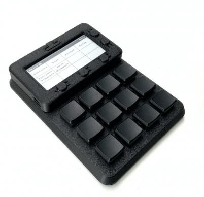
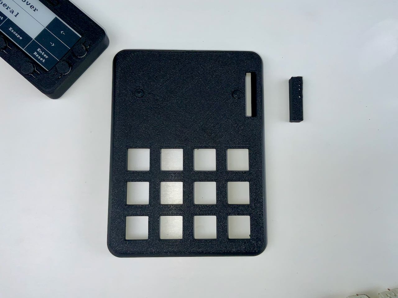
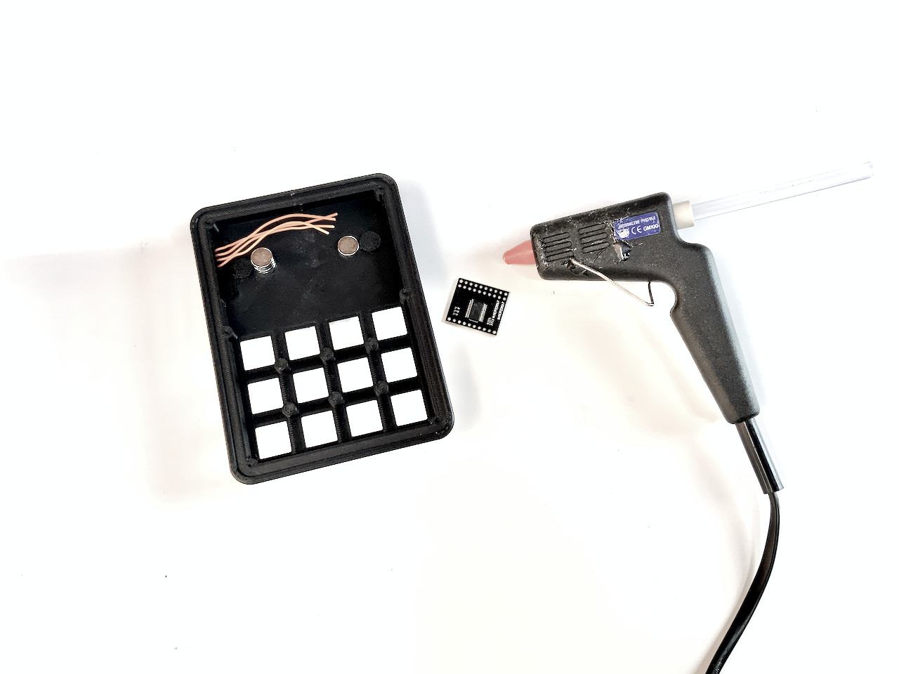
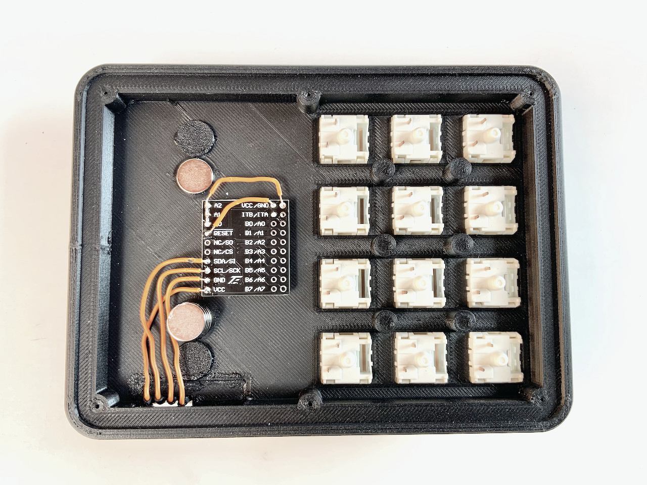
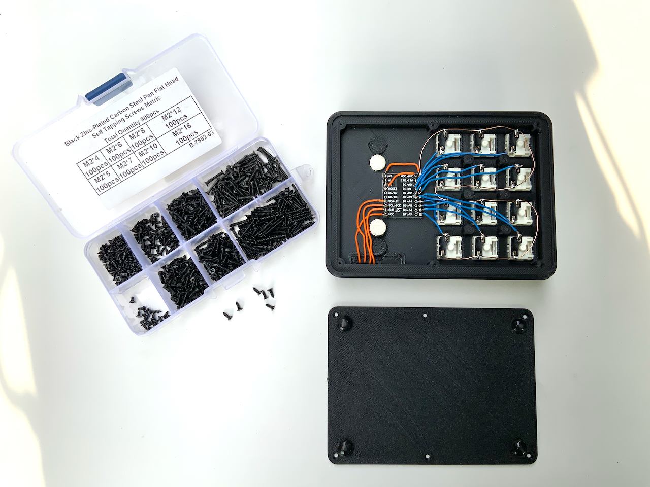
If you need more keys than the five on the badge, and you have a 3D printer, then I have something for you: an extension with 12 mechanical keys. You can use regular sized MX-keys (right picture) as well as the low profile keys from Kailh (left picture). The whole thing is wired by hand, but it's really easy to make.
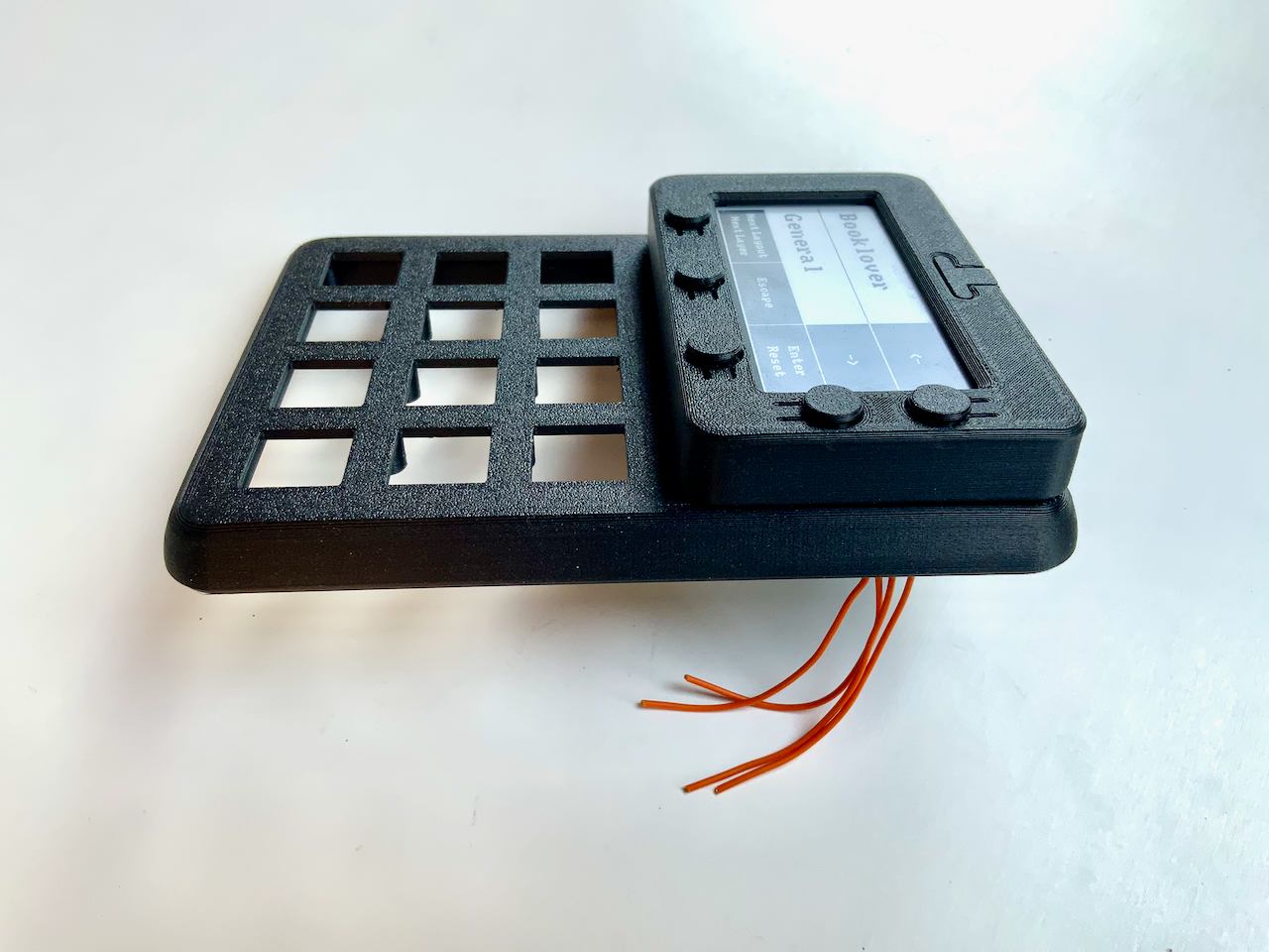
The badge is held magnetically on the keypad and can be easily attached or removed, because Pogo Pins are used for the electrical connection. You can even do this while the badge is connected to the computer.
The badge will then automatically switch to the appropriate mode. When plugged in, it shows the keyboard mapping of the additional keys and when operated without the external keyboard, it shows the mapping of its built-in keys.
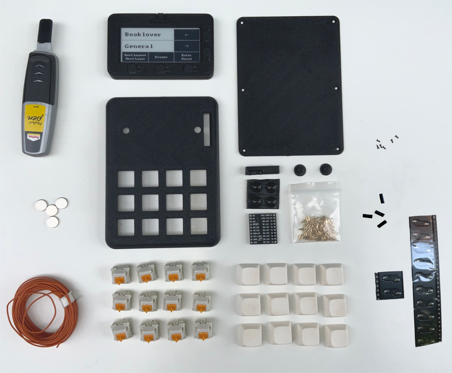
1. Parts
- 1 x Badger Enclosure
- 4 x 10mm x 2mm magnets
- 6 x 2mm x 5mm pointed screws
- 2 x Badger2040Keypad_Insert.stl
- 1 x Badger2040Keypad_Connector.stl
- 1 x Badger2040Keypad_Bottom.stl
- 1 x Badger2040Keypad_Top.stl
- 1 x MCP23017 / 16-Bit I/O expander
- 4 x Pogo pins
- 12 x Mechanical keys (MX)
- 12 x Keycaps
- 12 x Key sockets
- 1 x Hookup wire with a cross section of 0.2mm²
- 1 x Solder & soldering iron
- 4 x Heat shrink tubing
- 4 x Thin liquid super glue
- 4 x Rubber feed
STL Files
The files are hosted on printables
Pogo Pins
I know they are a bit expensive. You can also build the keyboard without the Pogo pins, and just use a cable with a Qwiic connector instead. In that case, the cable is fed through the connector hole and plugged into the socket on the back of the badge. If you want to do it this way, you don't need to print Connector.stl. But I recommend the variant with the Pogo Pins, because the Qwiic socket on the badge is not meant to be plugged in and out all the time. The socket can easily be damaged and it is not so easy to detach the badge from the keypad.
Keys
You need twelve mechanical keys. Both MX-style keys and low profile keys from Kailh fit into the keypad. And also twelve matching keycaps in the color of your choice. You don't necessarily need them, but I recommend key sockets, so you can change the keys later. They also make it easier to solder the cables to the keys, because they have a larger soldering area. I order my keys, keycaps and sockets here:
Heat shrink tubing
Short pieces of heat shrink tubing are put over the pogo pin connections. It is mainly a visual improvement because the pogo pins can be seen from the side. Use a color that matches your case.
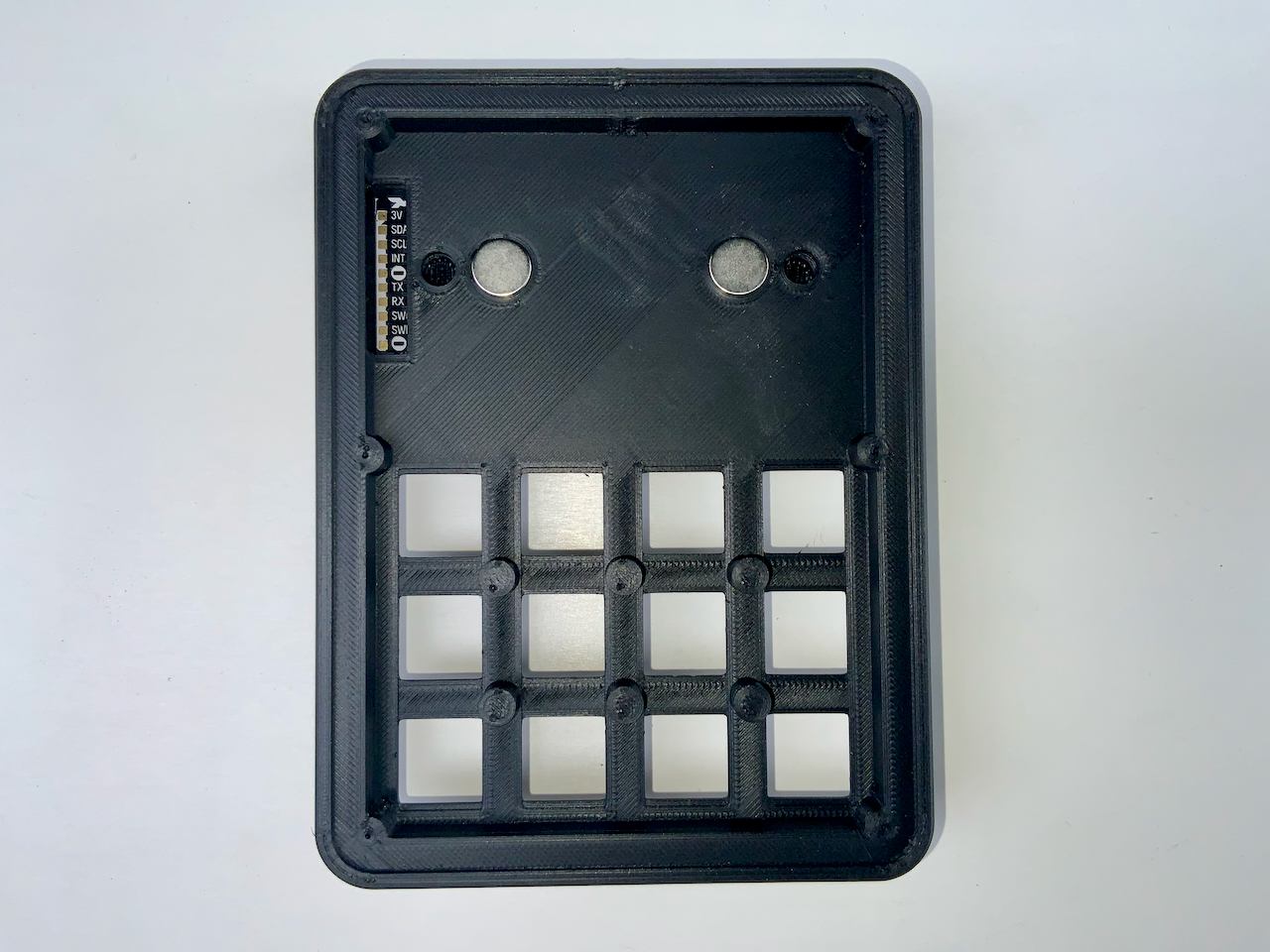
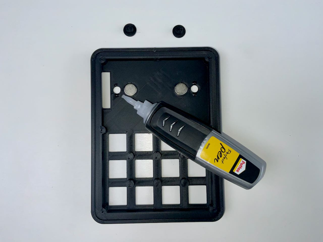
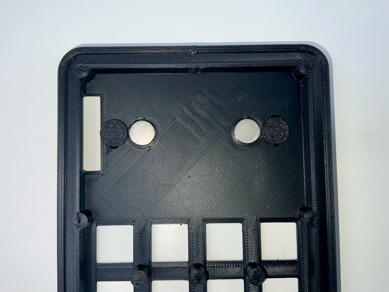
2. Magnets
Start by gluing two of the magnets into the designated spots with super glue. Hold the badge against it from behind so that the alignment of the magnets is correct. The magnets in the badge must attract the magnets in the keypad.
3. Inserts
The two inserts hold the badge in place. Glue them in with superglue.
3.2
3.3
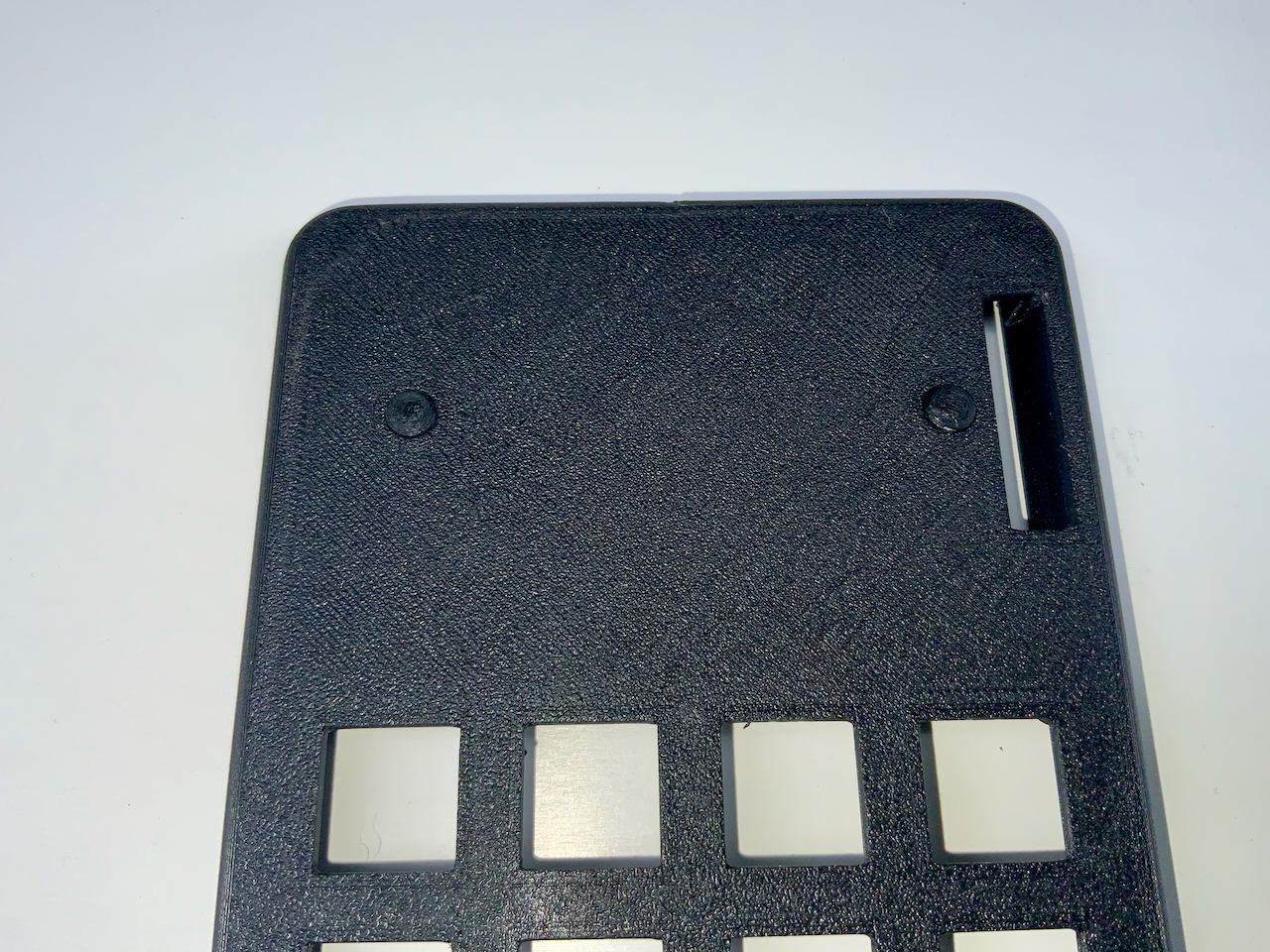
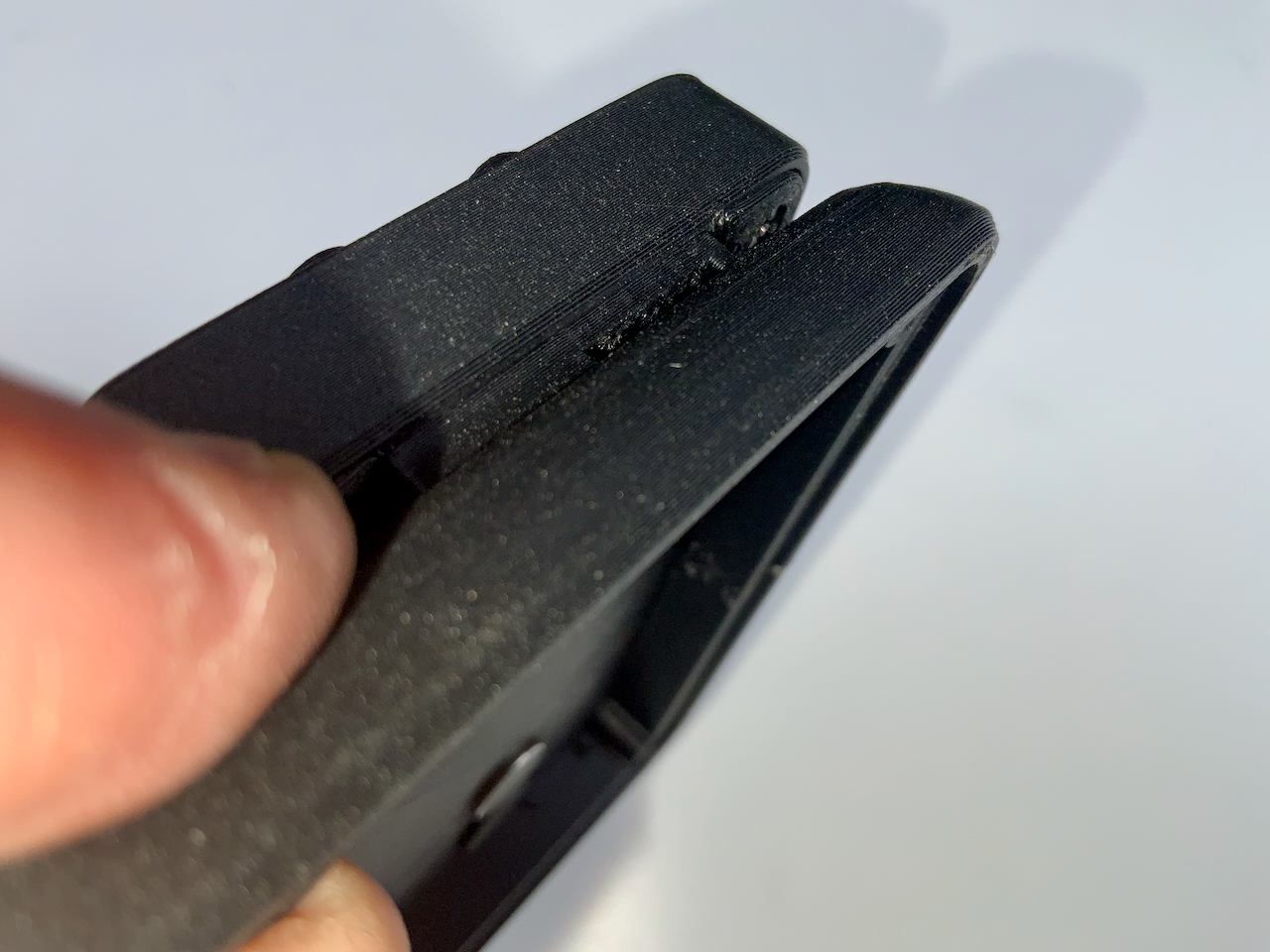
4. Connector preparation
Before you start working on the Pogo Pins, make sure that the connector can be inserted into the designated hole with some force. It should not be too loose so that you can adjust its position later on. If the part doesn't fit tightly into the hole, try printing it again with different settings.
4.2
4.3
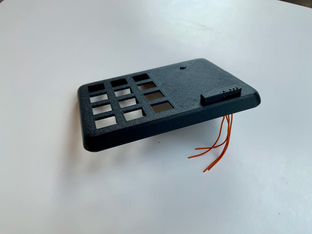
The connector should slide easily into the back of the badge.
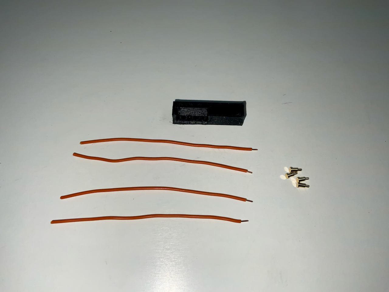
5. Pogo Pins
This is the first project I've used pogo pins in and I actually thought they would be difficult to handle, but it ends up being quite simple.
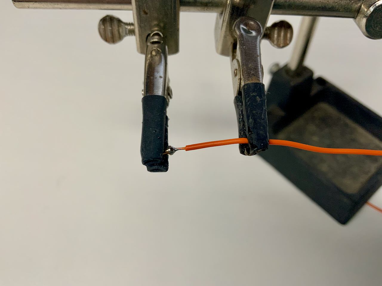
5.2
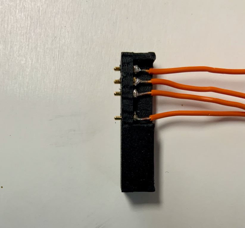
You can solder the cables against the back of the pins with the help of a third hand.
5.3
5.4
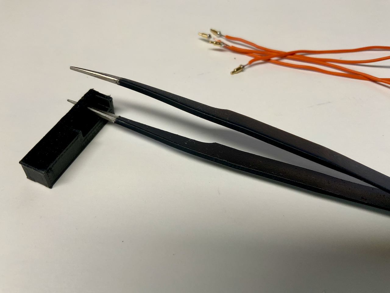
The holes in the connector are often too small for the Pogo Pins. You can widen them a bit with a pair of pointed tweezers. But not too much. You should be able to insert them with a little pressure.
5.5
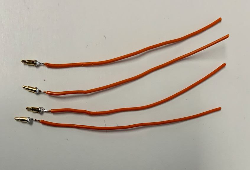
Make sure all pins stick out about the same length.
5.6
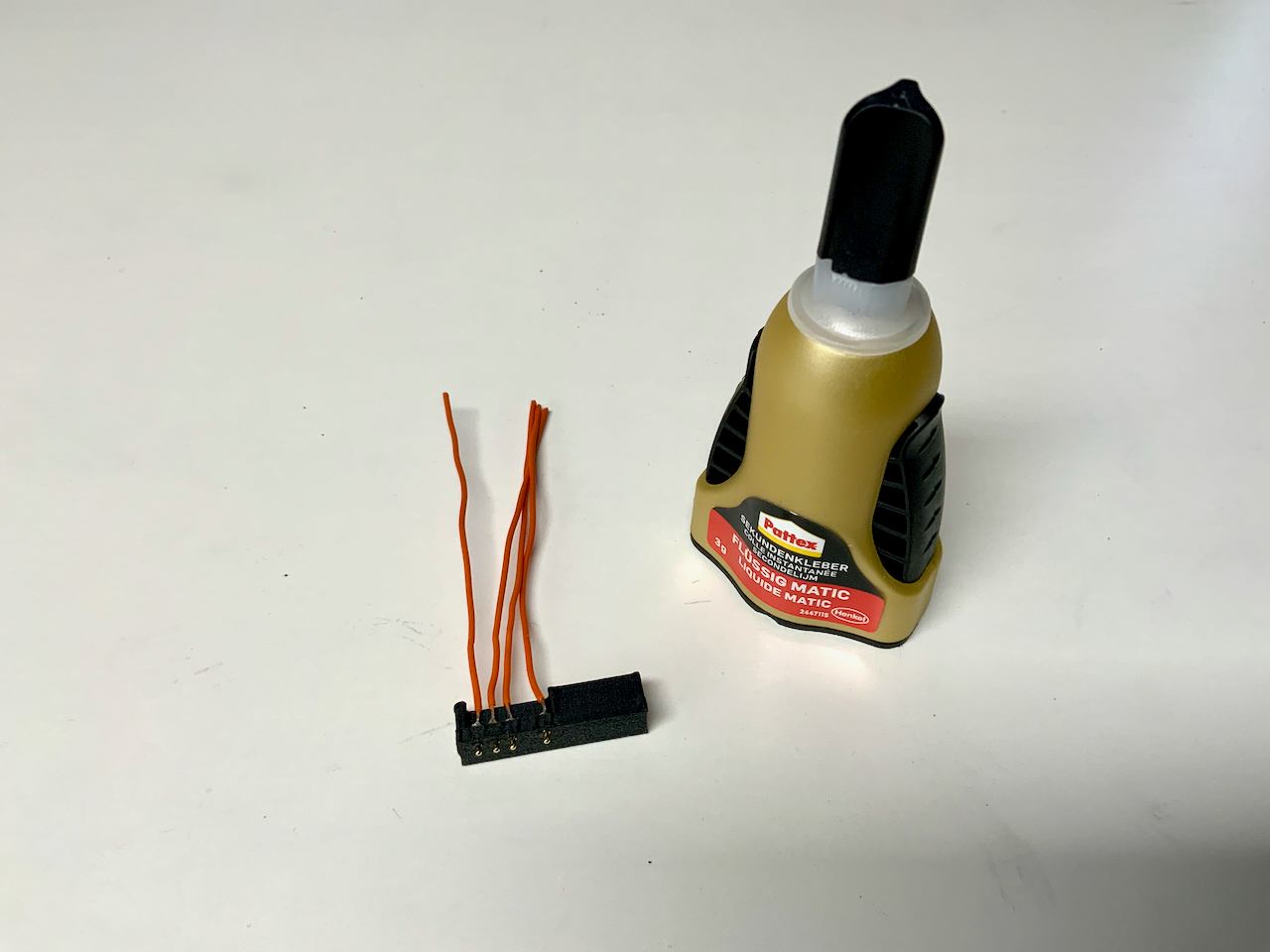
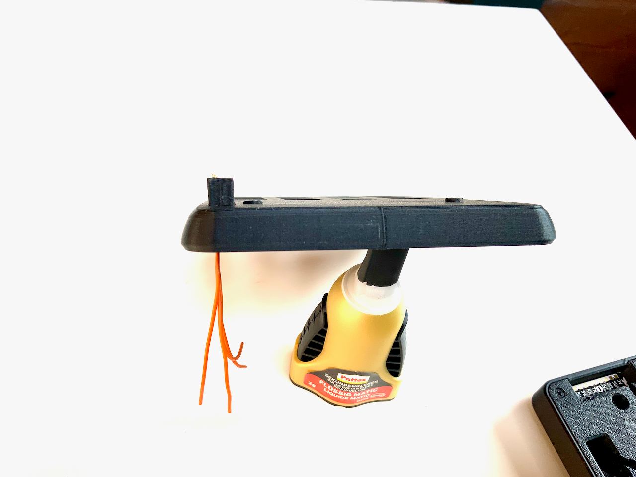
Use superglue on the backside to fix the pins, but do not use too much glue so that the spring mechanism is not damaged.
5.7
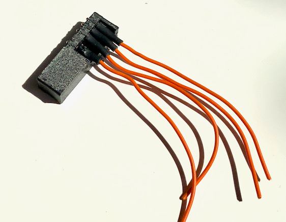
Insulate the cable connections with thin heat shrink tubing.
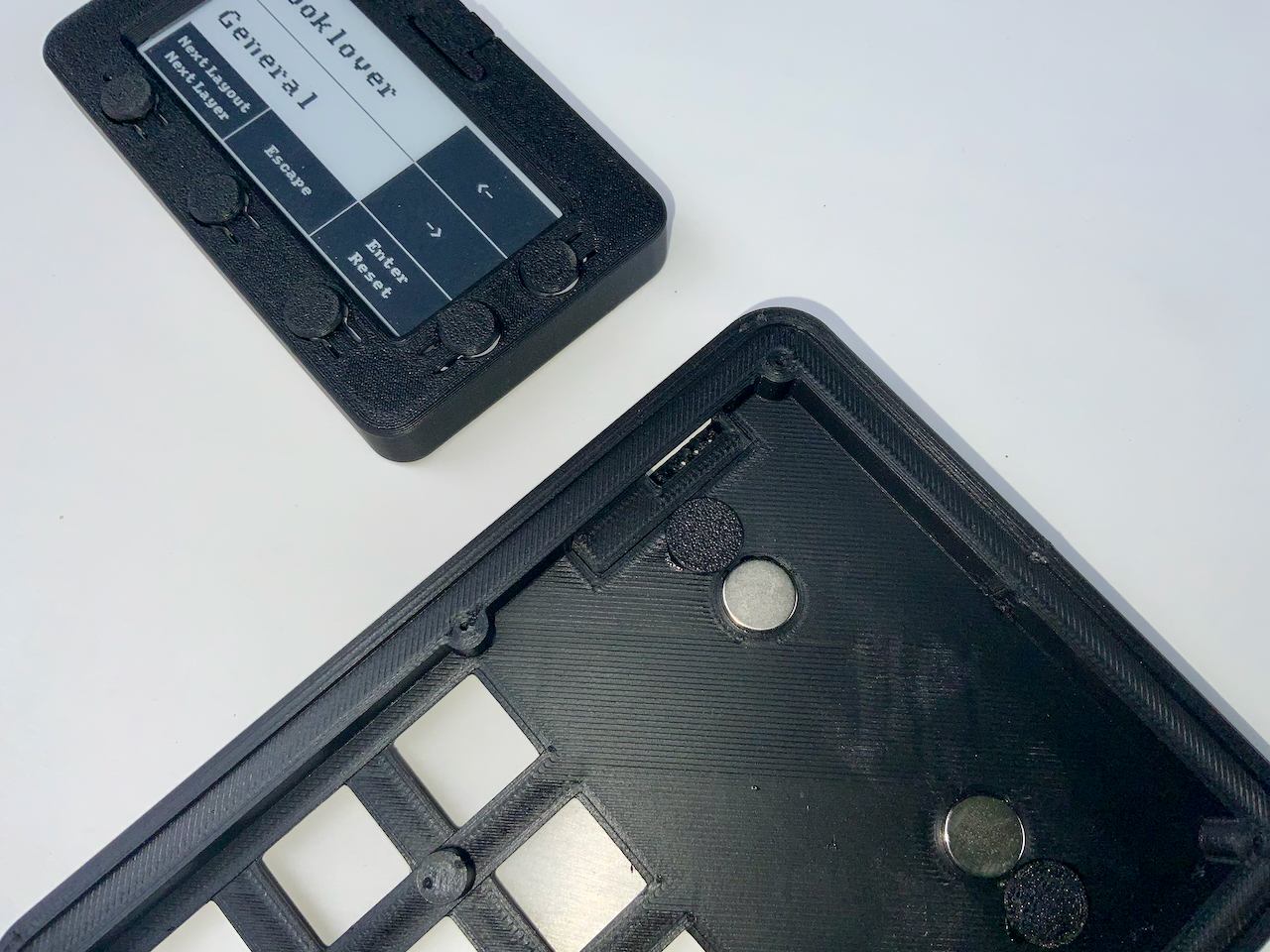
6. Connector
Insert the connector into the top part from above and then place the badge on the top part.
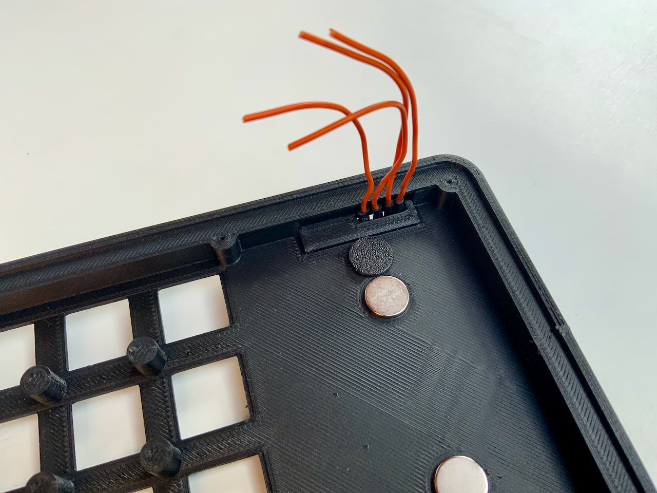
6.2
Press the connector from behind against the circuit board of the badge so that the pogo pins are pressed.
6.3
6.4
Remove the badge and make sure the connector is straight in the top. When you are satisfied with its position, glue it in place with a little superglue.
7. IO Expander
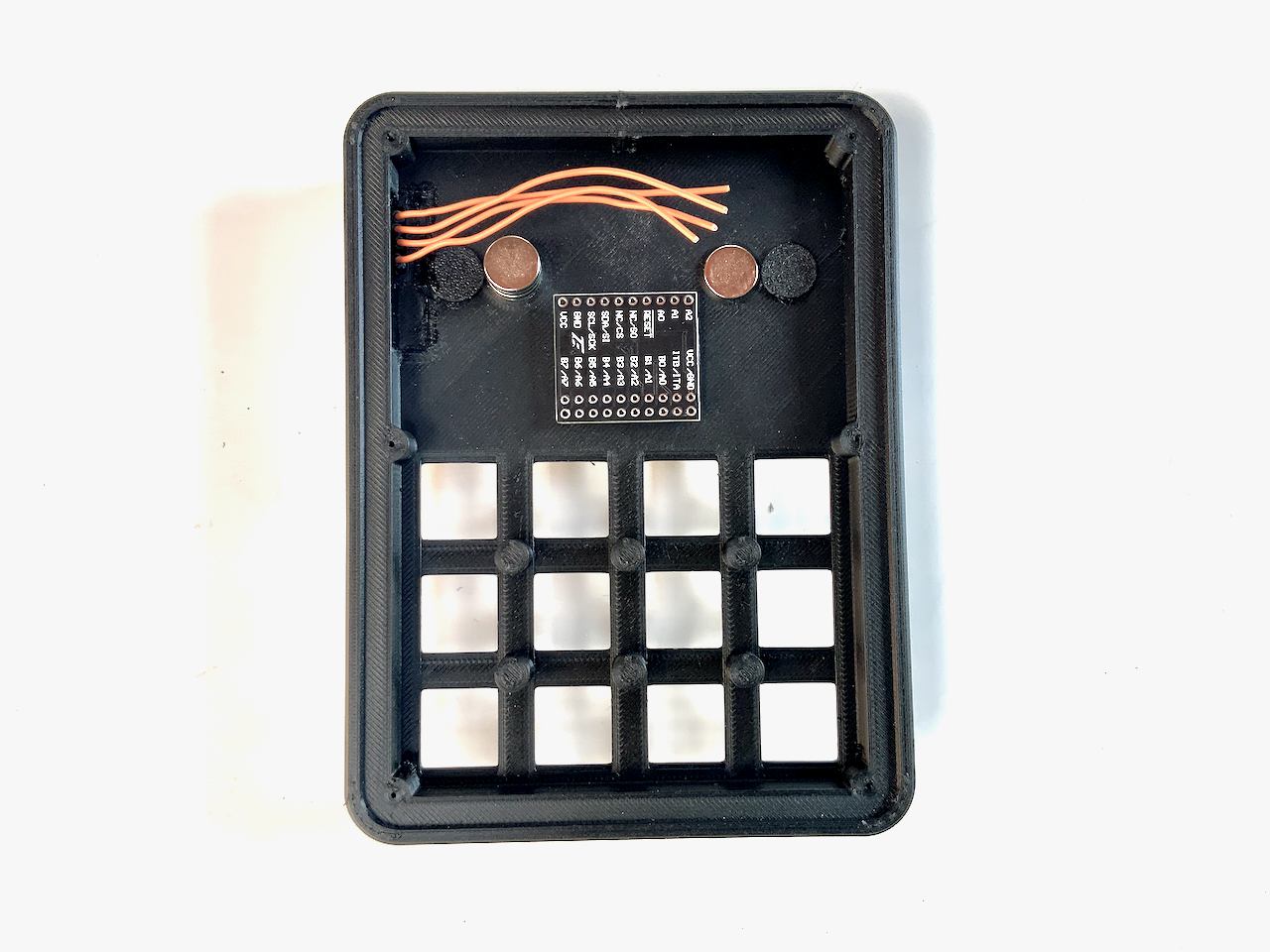
Der IO expander is a small PCB with an MCP23017 on it. Because there are so many different modules with this IC, I do not provide a mount for it. I simply attached my module with hot glue, making sure that the labeling is visible.
7.2
7.3
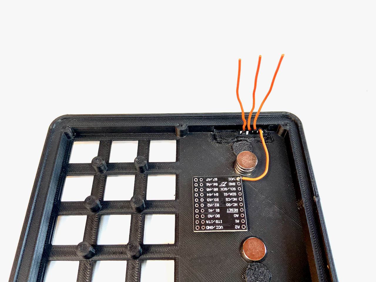
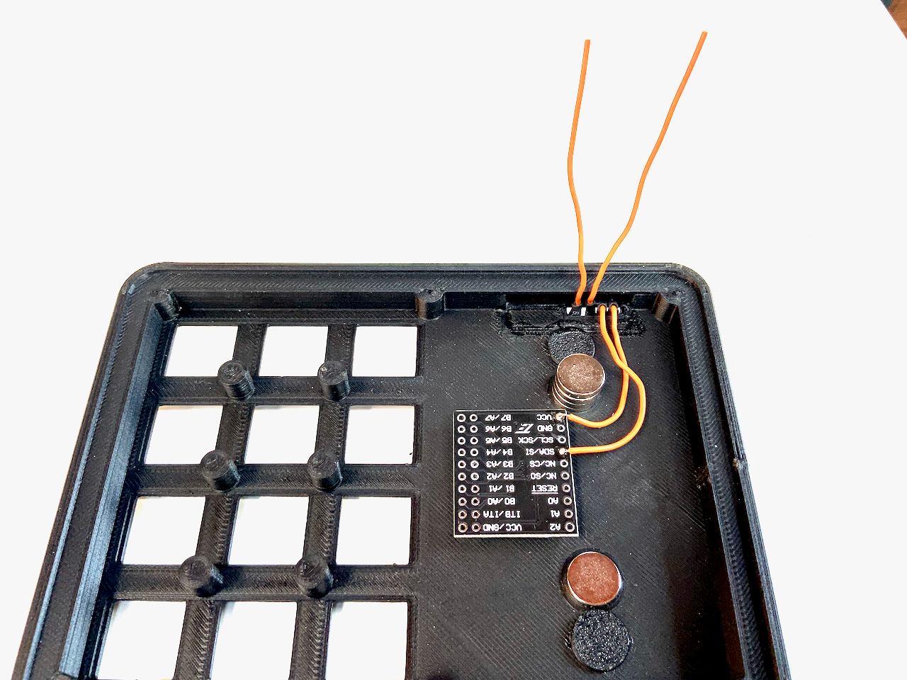
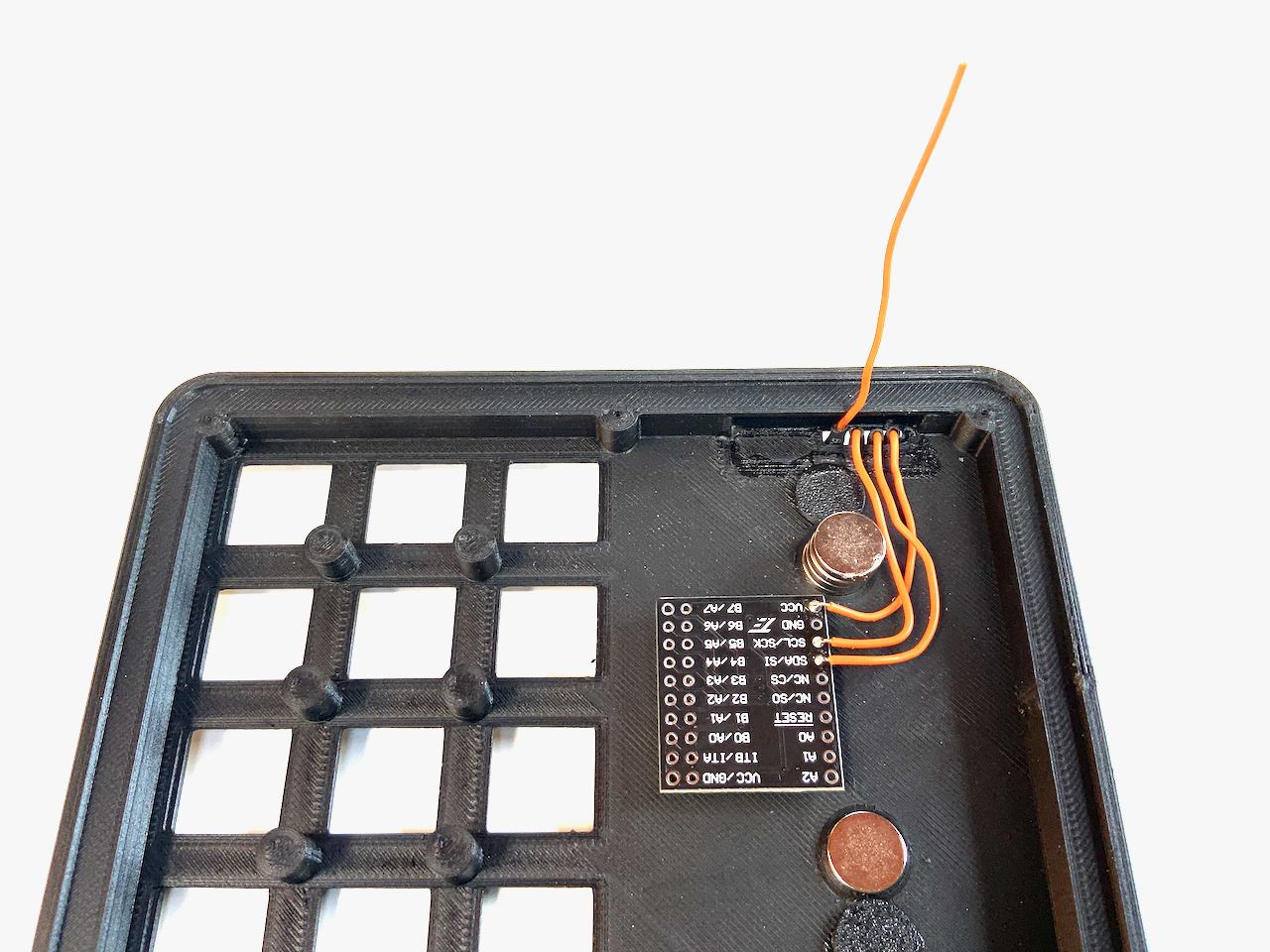
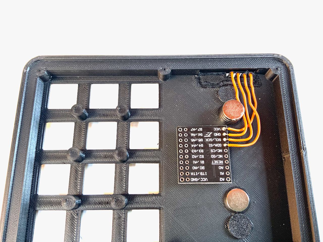
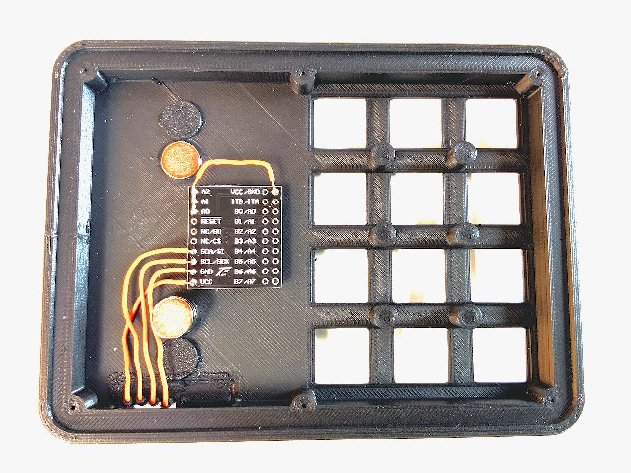
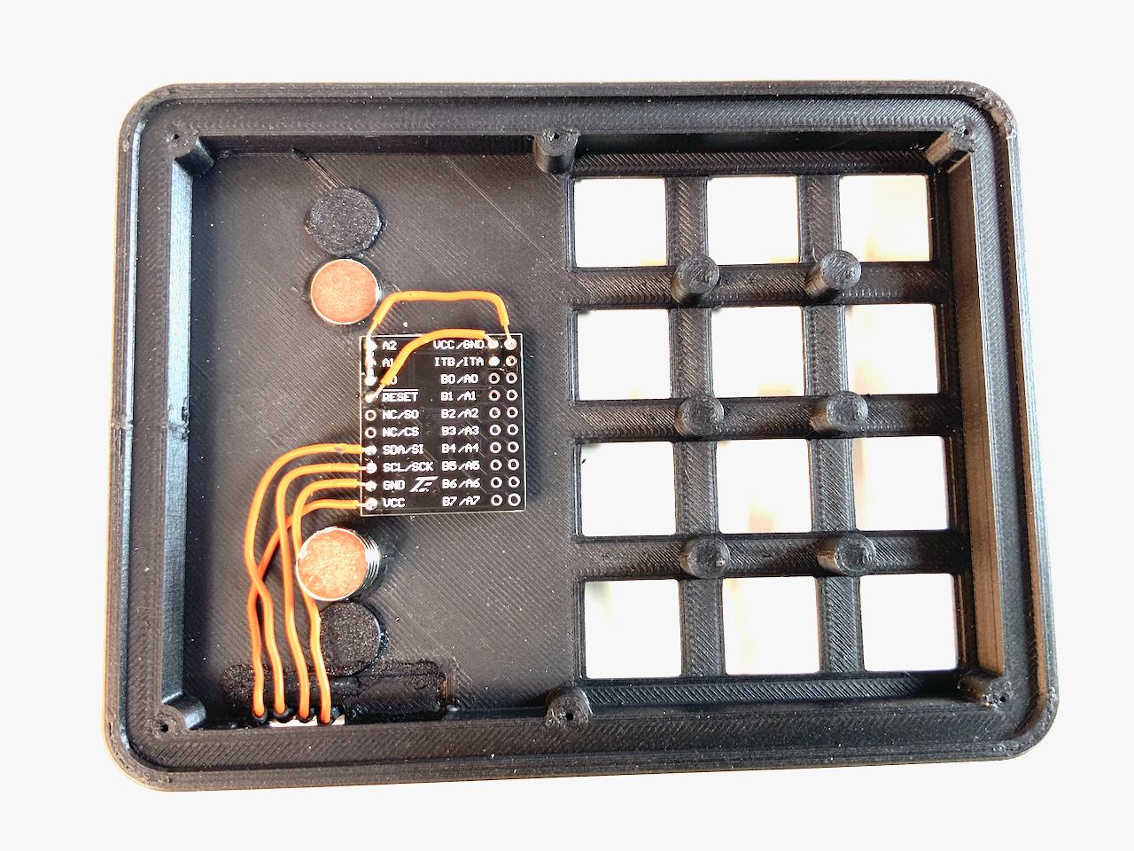
The following pictures show you how to connect the cables from the connector to the MCP23017 module.
7.4
7.5
7.6
7.7
All address pins are connected to GND
7.8
Reset is connected to VCC
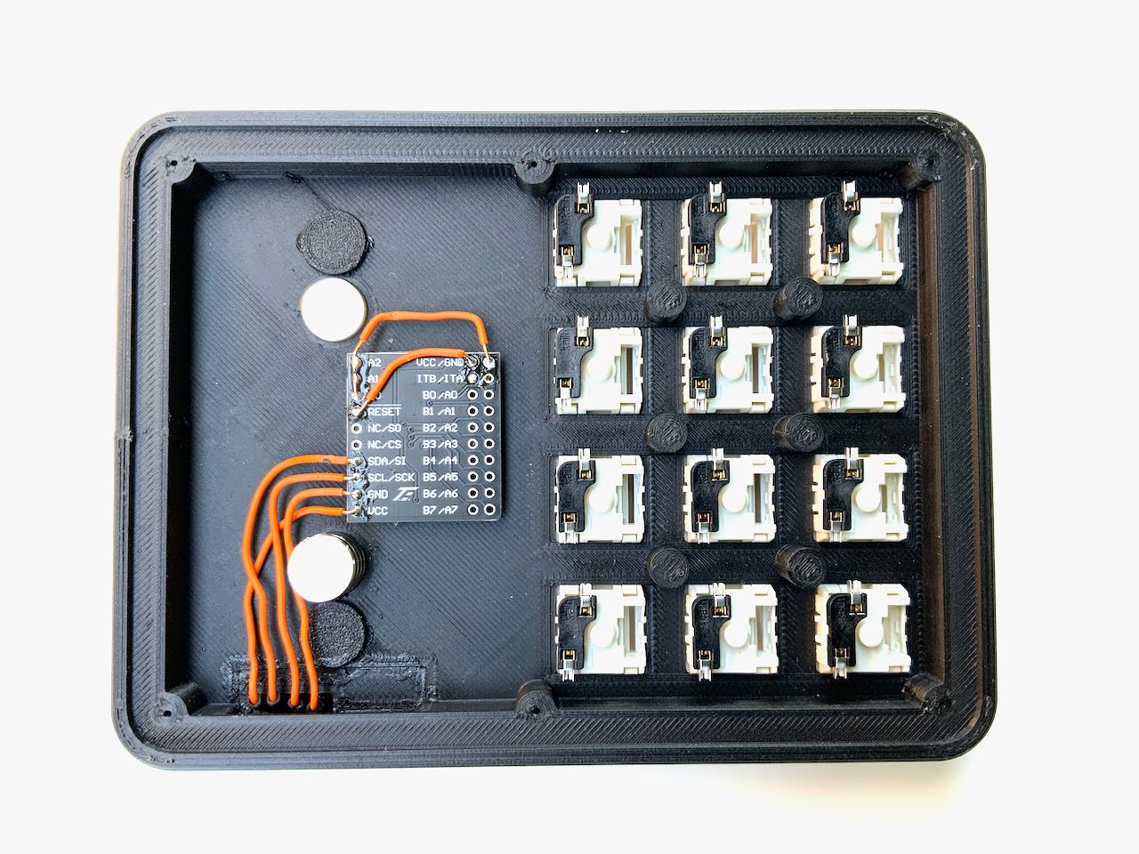
8. Key Switches
Insert twelve key switches. You can use MX-style key switches or low profile key switches from Kailh (I only tested the original low profile keys, not version 2).
8.2
Put sockets on the connectors of the switches if you want to change them at a later time. But even if you don't want to change them, I recommend the sockets, because you can solder the cables to them more easily.
8.3
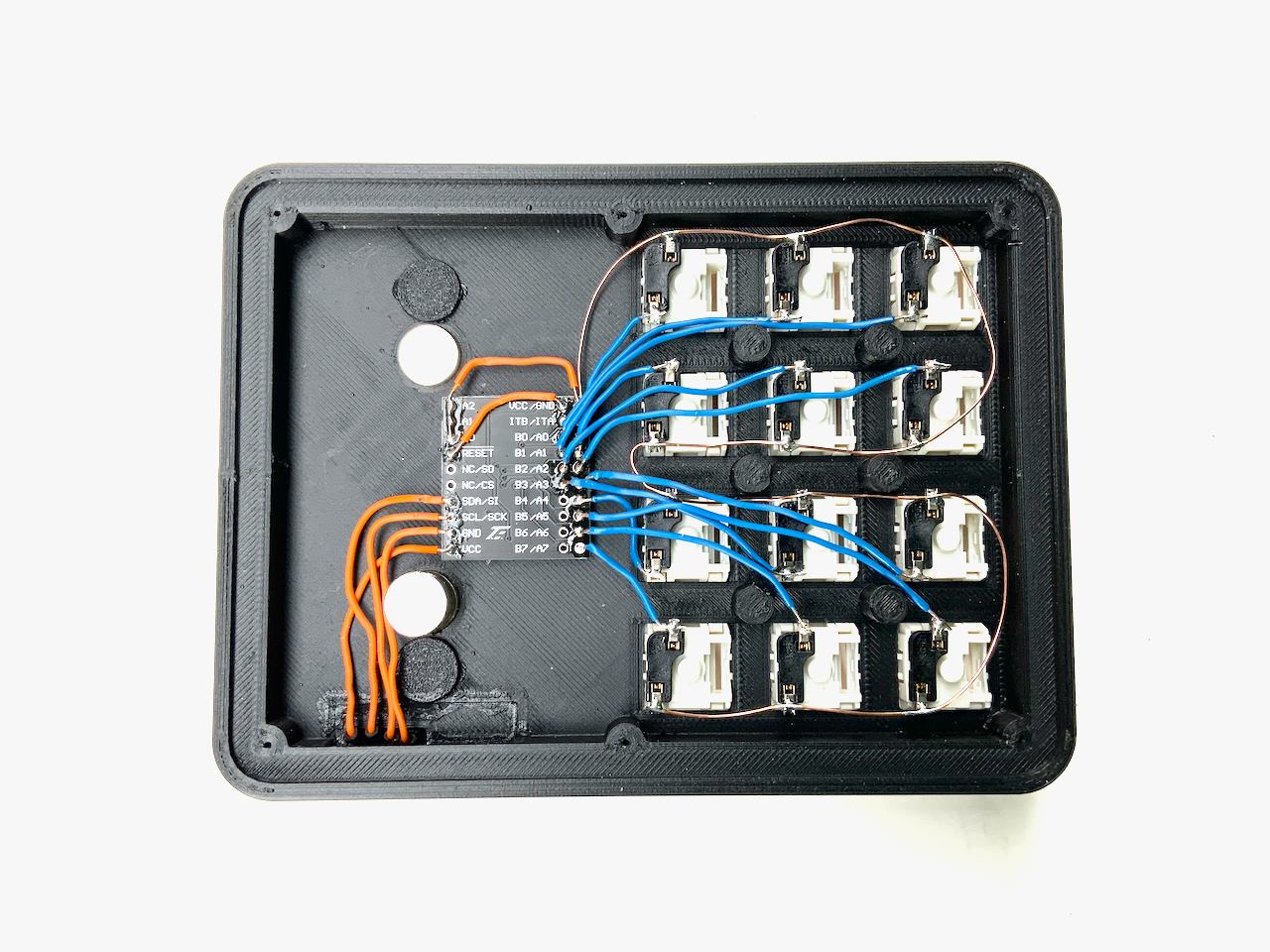
Connect one pin of each switch to GND
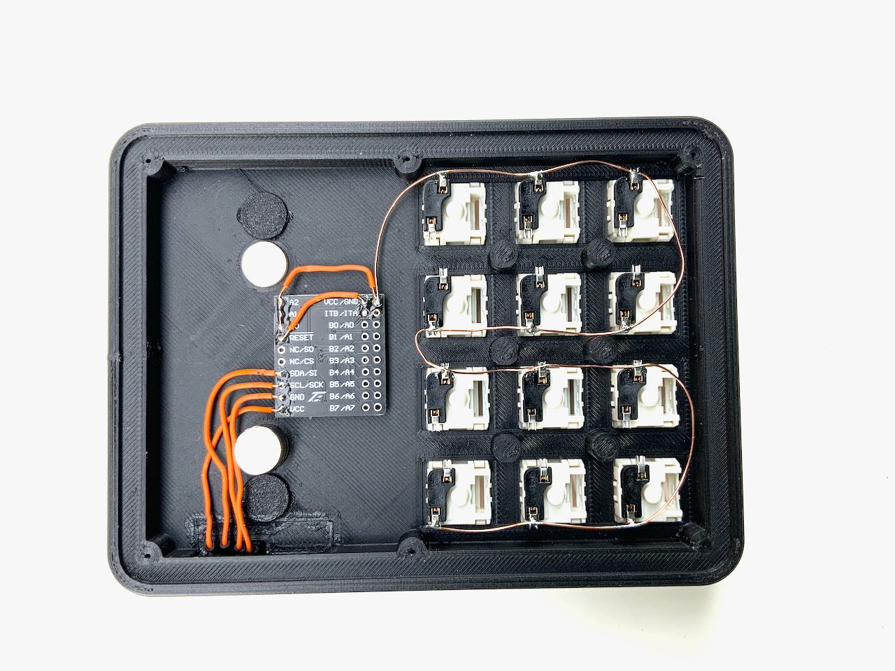
8.4
Connect the second pin of each switch to an input of the MCP23017 module. You can use all inputs except the last four (B4, B5, B6 and B7). Which key you solder to which pin does not matter.
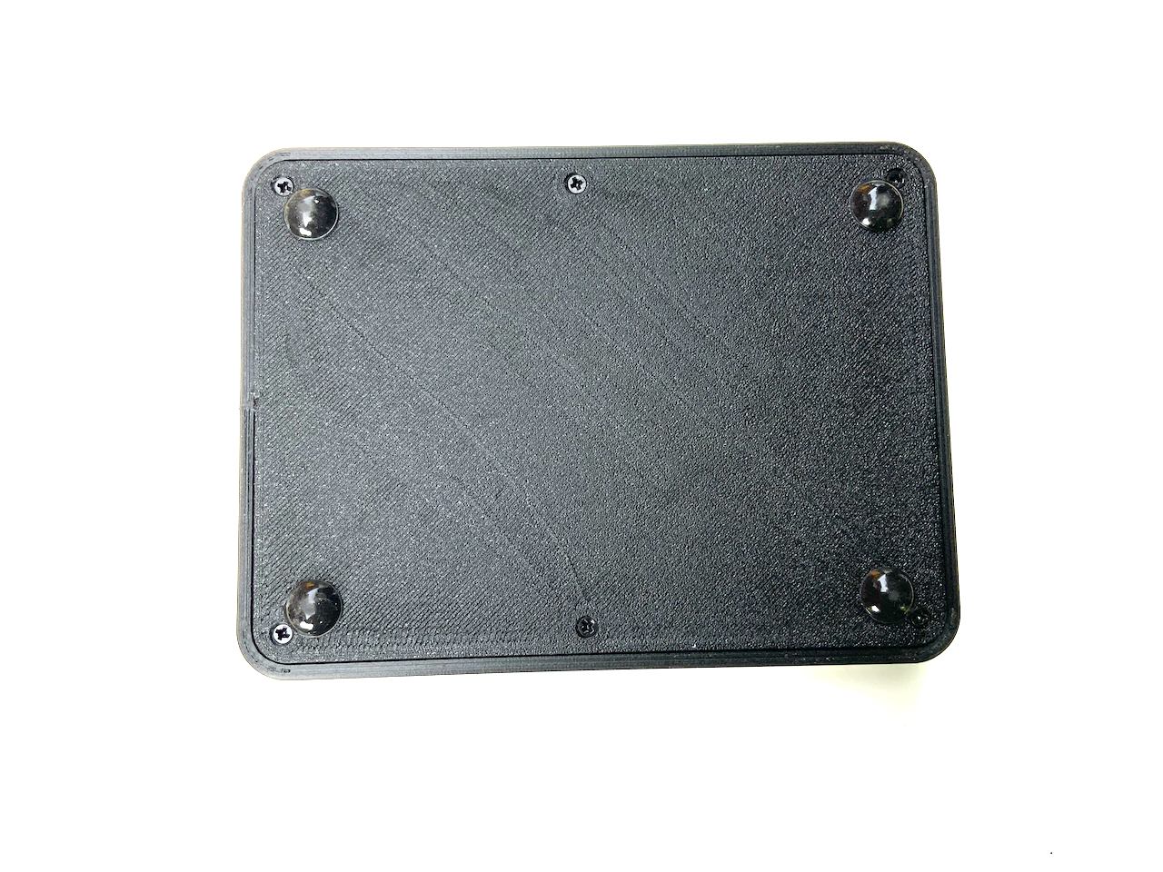
9. Bottom Plate
Now you're almost done with the hardware. You only have to fix the bottom plate to the top part with six 2 mm screws.
9.2
Firmware
The firmware for the Badger 2040 keypad is a derivative of my PicoSplit firmware. This firmware certainly has fewer features than some other firmware, but it comes with everything for configuration. You don't need to install any additional software on your computer. A simple text editor and a web browser is all you need. I provide the firmware for free under the MIT license. It is hosted on github.
Features
- Time-saving system for wiring the switches.
- No need to install any other software on your computer.
- Readable configuration file format.
- Easily modifiable with some Python knowledge.
- Advanced keyboard layouts are possible.
- Supports multiple layouts and each layout can have multiple layers.
Installing the firmware
The Badger 2040 Keypad firmware is based on CircuitPython version 7.3. Previous versions do not work. Go to https://circuitpython.org/board/pimoroni_badger2040/ and install CircuitPython on your badge. Then proceed with the next steps.
- Connect the badge with a USB cable to your computer.
- A USB memory drive with the name CIRCUITPY appears inside the Finder (macOS) or Explorer (Windows).
- Copy the files and folders inside the CIRCUITPY folder in the repository to that drive.
If you do not want to use an external keypad module skip Keypad module setup and Mapping hardware keys.
Keypad module setup
Quick function test with the keypad module
- Open an text editor
- Press all the keys on your keypad one after the other
Each time you press a key, a number should appear in the text editor and then the cursor should jump to the next line. If no number appears when you press a key, check the wiring of the corresponding key.
Mapping hardware keys
When we talk about a keyboard layout, we often mean two things: The arrangement of keys on a keyboard and the key assignment. In the Badger 2040 keypad firmware the layout term is used for the key assignment.
This firmware is designed to make the wiring as simple as possible. For example: the keys don't have to be connected to specific input pins of the MCP23017 in order to match a certain key arrangement (you can use all inputs except the last four: B4, B5, B6 and B7). This makes it easier to build handwired keyboards, because you can connect any key to any pin, as long as you use the pins you specified in the firmware.
The numbers you see when doing the quick function test are hardware key numbers. These hardware key numbers are mapped to standardized key numbers, which are used in the keyboard layout definition file (layout.js). This way you can use the same layout with differently wired keyboards.
The mapping from hardware key numbers to layout key numbers cannot be done automatically, because the system does not know how the keys are wired. But there is a tool for this task. Open the file PinMapper.html in a web browser and you will see the following page:
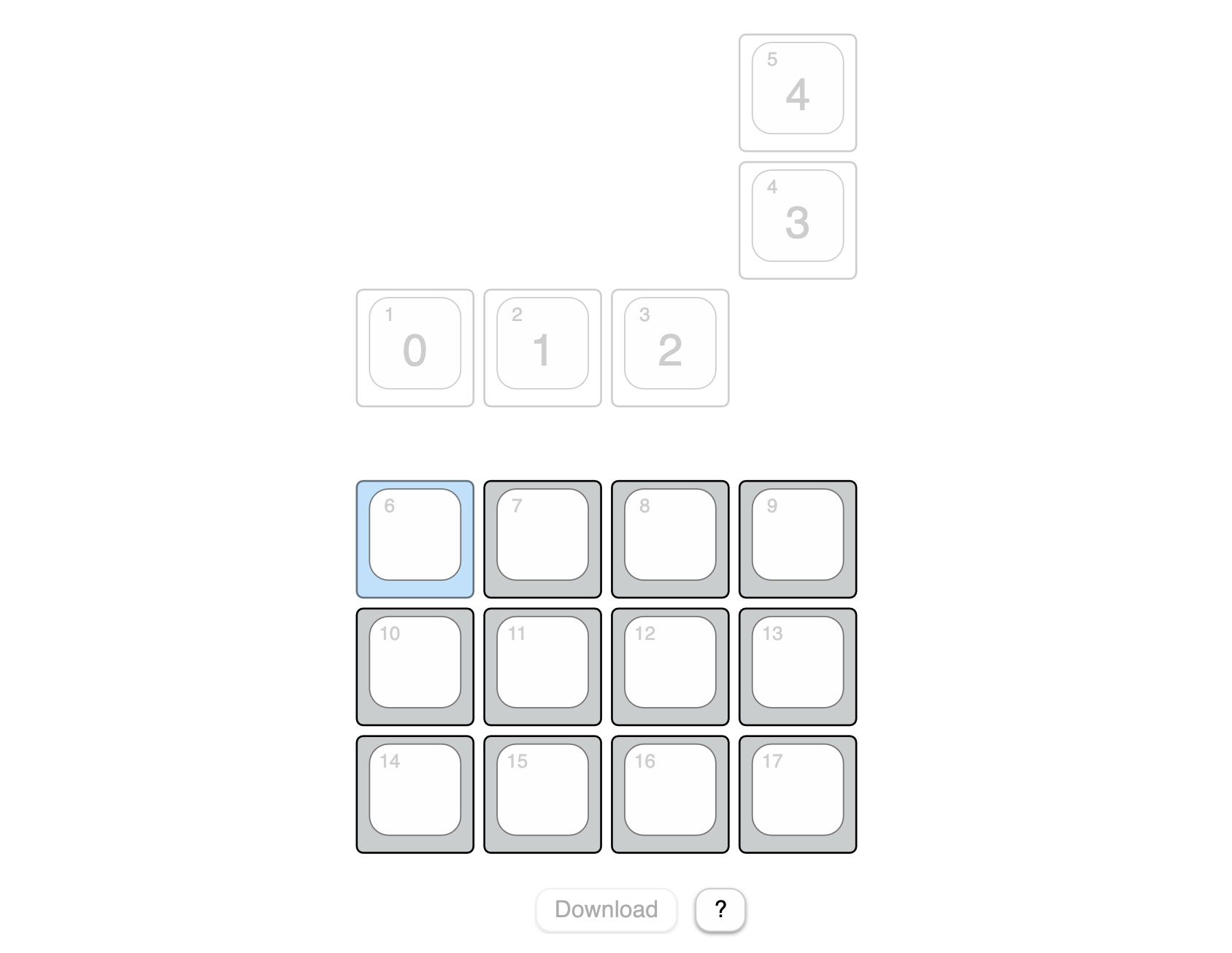
These are all the keys on the Badger 2040 when it is attached to the keypad module. The small number in the top left corner is the key number which is used inside the layout definition file (layout.js). The grayed-out keys built in to the badge have a fixed mapping that cannot be changed. They are displayed for reference purposes only. To map the hardware key numbers to the numbers used in layout.js, press the key on your keypad that is highlighted in blue.
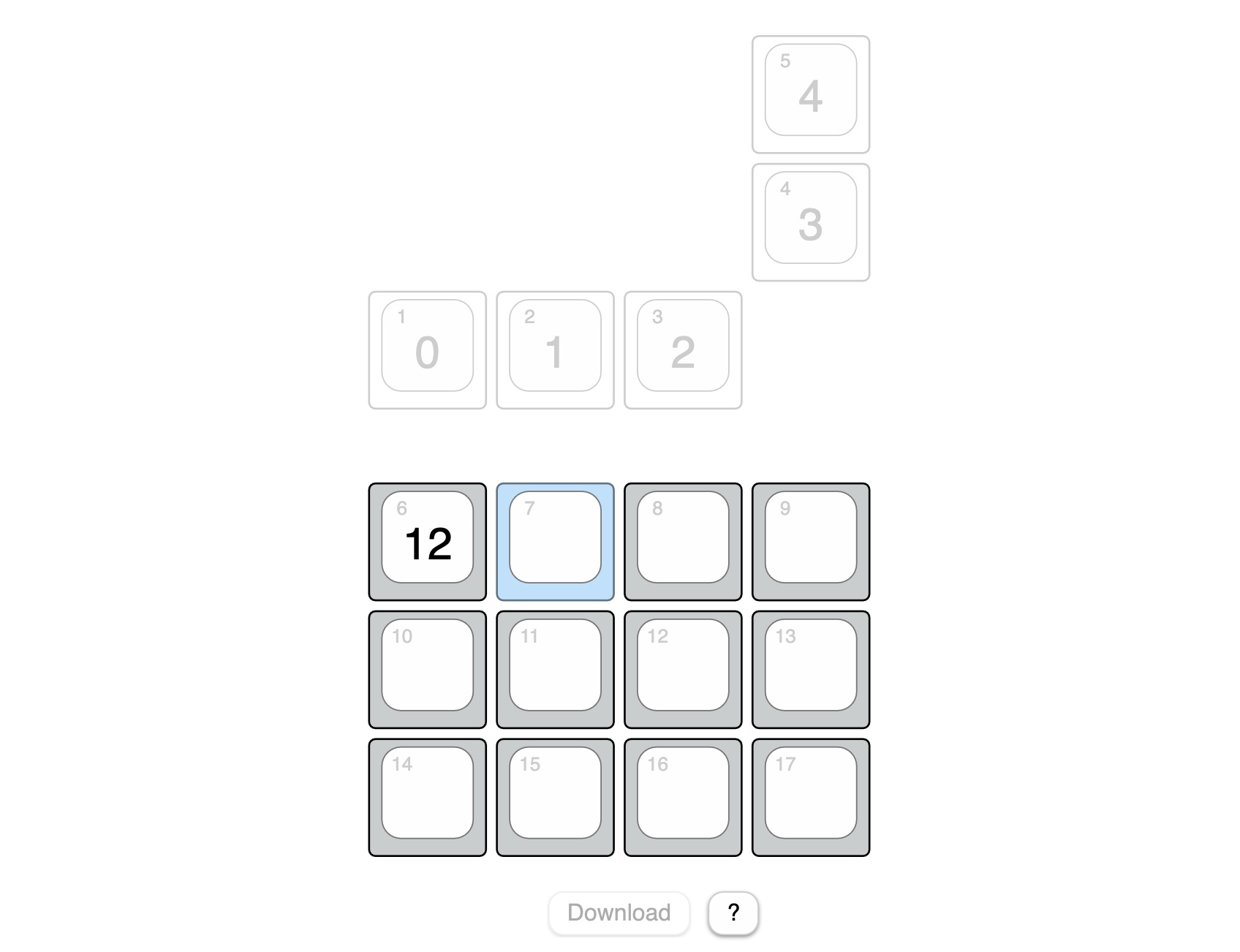
The recorded hardware key number is now visible at the center of the key (12). Then the next key is highlighted. Continue until you have pressed all the keys. You can always select a key with the mouse to change incorrect entries. When you have pressed all the keys, click the Download button. This will save a mapping.js file in your downloads folder. Copy this file to your keyboard.
If a mapping.js file is available on the keyboard, the keyboard stops emitting hardware key numbers and instead emits the key codes defined by the rules in layout.js.
Layout definition files
The badge can be operated in two modes:
- Without the keypad module. In that case, the description is read from standalone_layout.js.
- With the keypad module, the description is read from layout.js.
If you wonder why these and other files have the extension .js: They can be loaded as Javascript into a locally opened HTML page. For example: PinMapper.html uses this mechanism to read the key positions from keypositions.js.
There is actually no HTML based tool for managing layout.js and standalone_layout.js, but maybe there will be one in the future.
Sections
layout.js and standalone_layout.js consist of sections. Each section begins with a section keyword in one line and ends with the next empty line. These are the three available section types:
- keyboard
- layout
- layer
The order and count is important. It starts with a single keyboard section, followed by one ore more layout sections which each containing one or more layer sections.
Keyboard section
The keyboard section defines some timeouts which apply to all keys.
keyboard
tap_timeout=0.15
long_tap_timeout=0.4
To describe these values, I would like to briefly discuss various action triggers. The firmware supports three triggers for each key:
- tap
- long_tap
- hold
A tap action is triggered when you press and release a key before tap_timeout (in seconds).
A long tap action is triggered when you press a key longer than tap_timeout but release it before long_tap_timeout (in seconds). In combination with the Shift action, which will be described later, you can for example type a capital letter, just by holding the key down a little longer.
A hold action is immediately triggered when you press a key. If you release the key before long_tap_timeout the hold action is released before a tap or long tap is triggered. If you press the key longer than long_tap_timeout, the hold action is released when you release the key. Its action does not affect a tap or long tap if it emits modifier keys or switches to another layer.
You are probably wondering what this is good for? With the hold action you can assign modifiers to keys which are normally used to type characters. Hold actions are also used to activate some layers.
Layout section
A layout section has just one property, the title of the layout. This title can be used in a ChangLayer() action to reference a layer.
layout
title=Booklover
Layer section
A layer has a title. It contains rules for action triggers (tap, long_tap or hold). There must be at least one layer - the base layer - and you can define multiple additional layers. Only one layer can be active at any time. However, rules do not have to be defined for all keys on each layer. For keys without a rule, the rule from the base layer is used.
Here is an example with all three action triggers and some of the actions:
layer
title=Base
1 : tap=NextLayout : long_tap=NextLayer : title=Next Layout\nNext Layer
2 : tap=Codes[ ESCAPE ] : title=Escape
3 : tap=Codes[ ENTER ] : long_tap=ResetKeyboard : title=Enter\nReset
4 : tap=Codes[ RIGHT_ARROW ] : title=->
5 : tap=Codes[ LEFT_ARROW ] : title=<-
A line which describes rules for a key starts with the key number followed by at least one rule. A rule consists of the action trigger name (tap, long_tap or hold) followed by the equal sign and the action. Rules are separated by colons.
Each line can have a optional title part. If a title is given it is shown up on the display for the key. You can use up to three lines by specifying line breaks with \n.
Available actions
Codes[ < Keycode >, < Keycode >, … ] emits the given key codes at the same time. See Keycodes.html for all available key codes.
Sequence[ < Action > ; < Action > ] emits the given actions one after the other. Sequences are currently not nestable and are only tested with Code actions. Note: The separator between actions inside sequences is a semicolon.
Shift Can be triggered by a long_tap and is only usefull if a tap action exists. It triggers the tap action and emits the key code for the shift key at the same time. This is used to emit capitalized letters on a long tap.
NextLayout activates the first layer of the next layout.
PreviousLayout activates the first layer of the previous layout.
SwitchLayout( < layout name > ) permanently activates the layout with the given name.
NextLayer activates the next layer of the active layout.
PreviousLayer activates the previous layer of the active layout.
ChangeLayer( < layer name > ) temporarily activates the layer with the given name as long as the trigger (tap or hold) is active. Note: the display does not show temporary layer changes because it is too slow for that.
SwitchLayer( < layer name > ) permanently activates the layer with the given name.
ResetKeyboard restarts / resets the badge.
Boot behavior
The firmware has a maintenance mode in which a USB memory drive with all configuration files shows up. The keyboard is automatically in maintenance mode if no mapping.js file is on the memory drive. You can manually enter maintenance mode by resetting or reconnecting the keyboard to the computer while pressing and holding one of the badge's built-in buttons.
If you want to always boot the keyboard in maintenance mode set maintenance_mode to True at the beginning of boot.py.
maintenance_mode = True