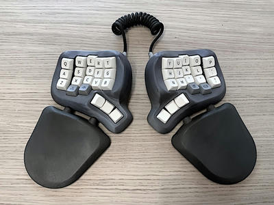
This 3D-printable keyboard, inspired by the Dactyl design, enables a natural and relaxed hand position even during long typing sessions due to its ergonomic shape. It offers interchangeable wrist rests, interchangeable switches and keycaps, a open-source firmware based on CircuitPython, and easy configuration via text files. It provides a time-saving wiring system without diodes and the flexibility to replace the Raspberry Pi Pico with other microcontrollers if needed.
The STL files are hosted on printables
Have you ever thought about how many hours a day you spend in front of the computer with the keyboard? I'm a software developer and for me it's certainly more than 8 hours, because the keyboard is my most important input tool. I can't write software without it. Even though that's the case, for years - decades, actually - I typed with just a few fingers. I kept glancing back and forth between the keyboard and the screen.
My typing speed was okay, but the constant glances got in the way and therfore I started to learn the 10-finger typing system. I even started doing it several times, because I never lasted long. Mainly for two reasons:
- I got pain in my wrists.
- The keys on a normal keyboard are offset and I often had trouble hitting the right keys.
I therefore tried different ergonomic keyboards. In the end, I found split keyboards to be the best, because I can always arrange them so that my wrists are in a relaxed position. I like it even more when the keyboard halves are slightly raised, so that my hands are not completely flat on the keyboard. For me, this is the optimal hand position and the PicoSplit keyboard has such an inclination already built in.
Most split keyboards do not have keys in rows that offset horizontally from each other. This seems to solve my second problem as well. But often these keyboards have much less keys than you are used to. On one hand, this is good because the muscle memory has to remember fewer positions and the hands don't have to move so far. On the other hand, you can only emit the missing keys by activating layers. A layer has its own key assignment for each key.
That's why keyboard layout matters. As much as I liked my first split keyboard (it was the Kyria from Splitkb.com), I was undecided about the layout until one day I found the Miryoku layout.


The layout has very few keys and it is so well thought out that you can really type all characters of a normal keyboard with it. The basic layout corresponds to the English Colemak layout. There is also a qwerty variant, which I use in a slightly modified form in the PicoSplit keyboard:


You can change the layout of the PicoSplit with a text editor and without having to install any development environment. The firmware is based on CircuitPython which provides, beside the USB keyboard, a USB memory drive. Not only the configuration files are on this drive, but also the whole PicoSplit firmware in form of Python scripts.
Features
- 3D-printable with common FDM printers.
- Its shape is inspired by the Dactyl keyboard.
- Allows you to keep your hands natural and relaxed, even after hours of typing.
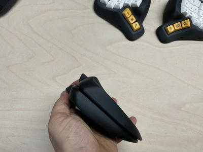
- Interchangeable wrist rests that magnetically dock to the keyboard.
- Adjustable distance between keyboard and wrist rests.
- Keyboard and wrist rests can be magnetically attached to a surface.
- Keyboard halves snap together for transport.
- Switches and keycaps are interchangeable.
- The PicoSplit keyboard firmware is open source and based on CircuitPython.
- Readable configuration file format.
- Easily modifiable firmware
- Time-saving system for wiring the switches without having to use diodes.
- No need to install any other software on your computer.
- A simple text editor is all you need to modify the keyboard layout.
- A layout that reduces finger travel a lot is already included. It is inspired by the Miryoku layout.
- The Raspberry Pi Pico can be replaced by something else thanks to slide-in modules.
Limitations
The PicoSplit firmware is based on CircuitPython. Currently USB keyboards created with CircuitPython do not work in all situations. For example: On my Intel iMac (macOS 11.x), I can not enter the login password if the hard disk is encrypted and waking up that Mac from sleep by pressing a key on the PicoSplit does not work (see discussion). You may encounter similar problems on Windows and Linux. On the other hand, I can use the PicoSplit with a M1 MacBook without problems and it works with my iOS and Android devices. So it depends.
Overview
3D printed parts
The plastic parts are easiest to print with PLA. A keyboard case weighs about 200g including support material. A wrist rest weighs about 100g. All parts together weigh a little under 600g. This includes 120g for support material. I have had good experiences with PolyTerra PLA. It's not expensive, has a nice matte finish, and prints easily. I printed the parts you see here with that material.
Magnets
40 neodymium magnets measuring 10 x 2mm. These will fit: Magenesis Neodymium 10x2 mm 52 pieces Mini Magnets Extremely Strong approx. 2 kilo adhesive strength, 10 x 2 mm : Amazon.com: business, industry & scienceYou'll need at least 40 neodymium magnets measuring 10 x 2mm. These will fit: Magenesis Neodymium 10x2 mm 52 pieces Mini Magnets Extremely Strong approx. 2 kilo adhesive strength, 10 x 2 mm : Amazon.com: business, industry & science
Rubber feet
Rubber feet not only prevent the keyboard from slipping, but also serve as a buffer between the keyboard and the wrist rest. The optimal shape for the buffer rubber is a ball section with a base diameter of about 9-10mm. This shape is also good for the feet, as it is more slip-resistant than other shapes. Therefore, I recommend these feet for both purposes: SAIYU Rubber Feet Pads 100 Pieces Adhesive Bumper Pad Silicone Bumper Foot Protector Pad (100 Pieces, 9mm x 3mm, Black, Hemispherical Shape) : Amazon.com: hardware store
Screws
30 x M2 x 5mm screws. Single screws are hard to get, but in this set they are included: 800 pieces M2 black carbon steel with countersunk head and flat cross head, self-tapping screws, machine screws, fasteners, repair tools : Amazon.com: Hardware Store
Raspberry Pi Pico
You need two Raspberry Pi Pico microcontrollers. Some suppliers also offer pin headers. You don't need these pin headers. I bought mine here: Raspberry Pi Pico - Welectron
Glue
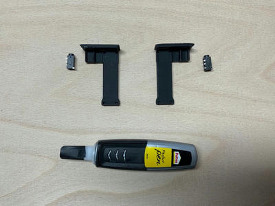
The magnets and the TRRS sockets are fixed with glue. A great alternative to epoxy is viscous superglue. This one works great: Pattex PSPP3 superglue Perfect Pen 3 g, black, 1 x 3g : Amazon.de: Baumarkt
Wire
You need at least 4.50 meters of copper wire with a diameter of 0.5 mm. It does not have to be in different colors, as shown in the picture above, but make sure that the cable does not consist of many small strands, but has a solid copper core.
TRRS jack
You need two TRRS jacks. Stores who offer accessories for do-it-yourself keyboards often have them as well: 2x TRRS jacks 3.5mm | Parts | Keyboard Parts | Keycapsss
TRRS cable
The TRRS cable is used to connect the two halves of the keyboard. One is enough. It should have a length of at least 30 cm, so that you can place the keyboard halves far apart if necessary: TRRS Cable 4-pole 3.5mm jack 30cm 12inch | Accessories | Keycapsss
Micro-USB cable
One of the Raspberry Pi Picos is connected to the computer with a Micro-USB cable. For example, with this one: Amazon Basics 7T9MV4 Connecting Cable, USB 2.0, USB-A male to Micro-USB-B male , 1.8 m, Black: Amazon.com: Computers & Accessories
Keys
You need a total of 40 mechanical keys. The selection is huge and everyone probably has their own idea of the perfect key. I've tried a lot. I like the sound of self-oiled Glorious Panda switches, for example. The Gazzew Boba U4 are very quiet but with a great pressure point. I also tried the Kailh Low Profile Choc Switches (V1). They also fit into the PicoSplit keyboard . But keep in mind that low-profile keys don't stick out that far, and at least that's inconvenient for the thumb keys. You may have to put something under the corresponding keycaps in order to fix this.
Here are a few links to German retailers who offer keys and keycaps:
Keycaps
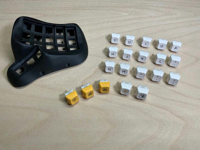
You need just as many keycaps as there are keys, i.e. 40 pieces. The keycaps must mechanically fit the keys and they must all be 1U keys (the smallest size). Most manufacturers copy the Cherry MX system and there is a huge variety in this universe.
Keycaps come in different shapes:


Kailh Low Profile Choc Keys (V1) also fit, but there are significantly fewer keycaps for this system and you need to raise the thump keycaps a little bit. Therefore I can not recommend these switches.
The keycaps used in this building instructions can be found on Aliexpress: [milk honey keycaps - Buy milk honey keycaps with free shipping on AliExpress version] (https://de.aliexpress.com/af/milk-honey-keycaps.html?d=y&origin=n&SearchText=milk+honey+keycaps&catId=0&initiative_id=AS_20211003054555)
Hot swap sockets
You need 40 hot swap sockets to match your keys. These sockets are actually intended for mounting on circuit boards, but they also make manual wiring easier in the PicoSplit keyboard. On one hand, they stabilize the buttons' pins, which are prone to kinking, and on the other hand, they offer a larger soldering surface, which simplifies the soldering of the cables. Only with hot swap sockets, you are able to swap the buttons as you like. You can get hot swap sockets here: [Kailh Hotswap PCB Sockets 10 pcs | Parts | Keyboard Parts | Keycapsss] (https://keycapsss.com/keyboard-parts/parts/49/kailh-hotswap-pcb-sockets-10-pcs?number=KC10019_MX)
Make sure to choose sockets that fit your keys (MX or Choc system).
3D Printed Parts
Test Piece
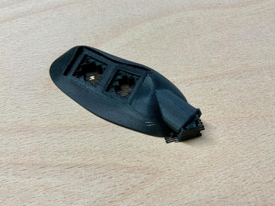
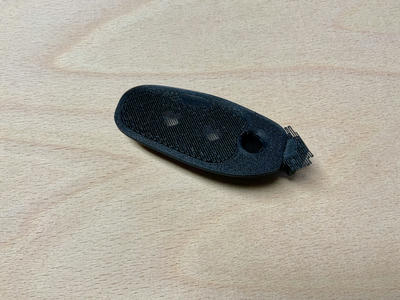
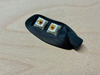
First of all, please print the test piece with support (download Test.stl.zip). The STL file contains a part with holes for a few buttons and holes for the magnets. These are the critical points that have to fit.
Testing fit
Make sure you can remove the support and you are able to insert the mechanical switches and that the switches are tight. You should be able to insert the 10 x 2 mm magnets without cracking the housing. With magnet B, a slight pressure may be necessary for this. Don't press magnet B all the way into the housing so you can get it out again (it is only a test piece).
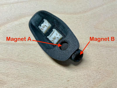
Slicer Settings
I create my own print files with the PrusaSlicer. For the keyboard I use a layer thickness of 0.15 mm. In addition, I activate the adaptive layer height. This reduces the layer thickness in some places, depending on the slope of the surface. With these settings, printing a keyboard case without a wrist rest takes about 25 hours, but the result is really good. And what are a few hours more for printing if you later work with the keyboard every day? I think it's worth it.
You will get the best surface with these PrusaSlicer settings:
- Layer Height: 0.15mm
- Horizontal shells, Solid layers, Top: 10
- Horizontal shells, Solid layers, Bottom: 10
- Infill, Fill density: 25%
- Variable layer height: Adaptive
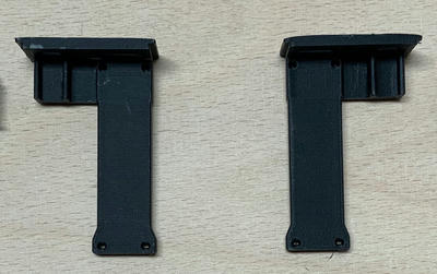
Slide-in modules and base plates
First print the two slide-in modules for the microcontrollers without support.
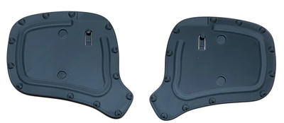
Next, the base plates. Here you don't need any support. By the way, the right side is not a mirror of the left side, even if it looks that way. The buttons are in different places.
Printing keyboard housings
Now print both keyboard housings (right and left) with support. In the picture you can see the finished print of the right keyboard housing from below.
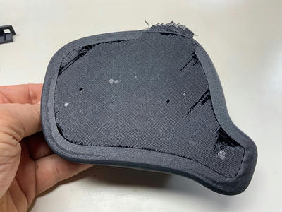
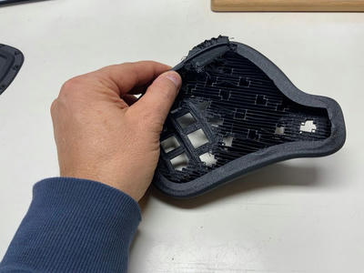
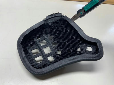
Removing support
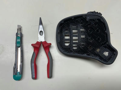
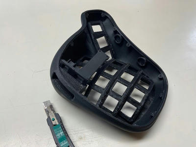
Remove the support and the thin skirt step by step. The skirt increases the adhesion to the print bed during printing. It will not be needed later on and you can remove it with a cutter.
Remove the remaining support material with needle-nose pliers.
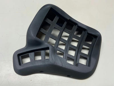
Cleaned housing
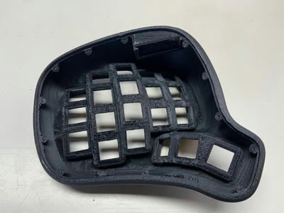
Your keyboard half should now look like this.
From above:
Checking slide-in module fit
At this stage you can check whether the slide-in module fits into the keyboard. Normally, it can easily be pushed into the slots. If not, remove some material from the slots or the sides of the module with a cutter.
Other keyboard housing
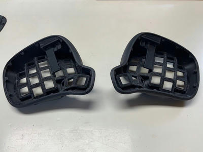
Proceed in the same way with the other keyboard housing.
Wrist rests
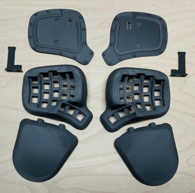
Finally, print the two wrist rests with support. Remove the support from the holes for the magnets. Here you can see all the printed parts.
Slide-In Modules
Mounting TRRS sockets
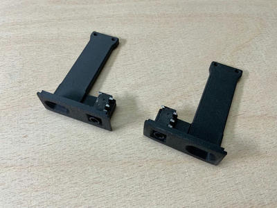
Glue the TRRS sockets into the slots with super glue.
This is how it should look like:
Fastening the Raspberry Pi Picos
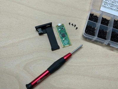
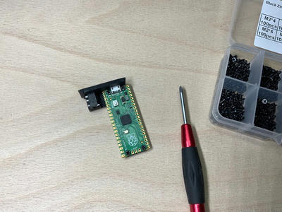
The Picos are attached to the slide-in modules with four 2 x 5 mm screws.
Marking ground pins
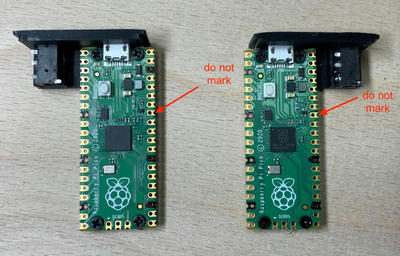
To avoid confusion when wiring the switches, mark the ground pins that are not needed with a permanent marker. Do not solder any cable to these marked pins later. Please do not skip this step. You can connect the switches to any input pin but the marked ground pins are not allowed. The risk of confusion without these markings is quite high.
Connecting the TRRS jacks
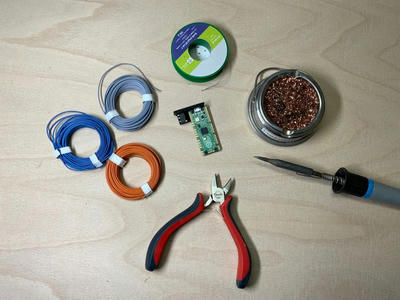
For the wiring you need a soldering iron, solder, a soldering sponge and a few centimeters of the 0.5 mm copper cable. I used different colored cables to show the connections clearly. Of course you can also use only one color.
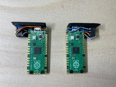
Finished cable routing
This is how the cable routing looks for both sides:
Magnets
Gluing magnets
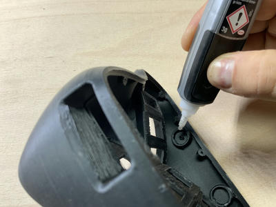
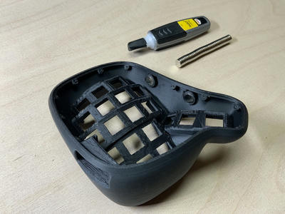
Use superglue to glue two magnets per keyboard housing into the holes provided. These magnets will later be used to attach the wrist rests. Align the magnets in both keyboard housings in the same way. For example, the north pole should always face outwards.
Magnet stack trick
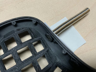
If you hold the remaining magnet stack against the case from the outside and use it to pull the magnet to be glued into the hole, you can be sure that it will maintain the specified orientation and not slip. The magnets are very strong and to avoid scratch marks, it is best to place a piece of paper between the magnet stack and the case.
Finish magnets
This is how it should look in the end:
Proceed in the same way with the other half of the keyboard.
Switches
Preparing keycaps
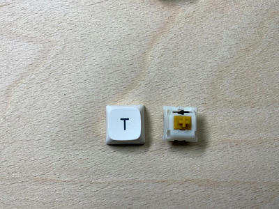
Put the keycaps on the 40 keys. If you have labeled keycaps, make sure the slot in the keycaps is on top.
Inserting keys
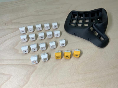
Insert the keys into the housings so that the slots are at the top. The thumb keys are the exception (see illustrations). Check whether all keys can be pressed down freely without jamming. The PicoSplit keyboard is optimized for short finger travel, so the keys are as close together as possible. If some keys do stick, then it may help if you rotate them. Normally nothing should stick, but you have to do this test now, because the keys will be soldered in the next step and then the alignment can't be changed anymore.
Hot plug sockets
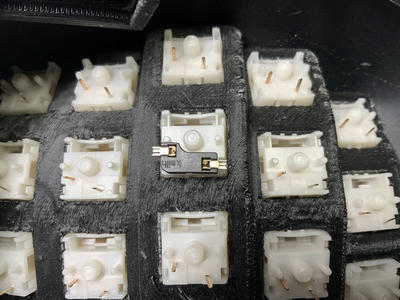
Now put the hot plug sockets onto the pins of the keys.
Insert the slide-in modules with the microcontrollers every now and then for test purposes, and make sure that the socket contacts do not touch the board.
Preparing ground wire
Now you need a piece of the copper cable with a length of about 70 cm. Remove the insulation from the cable.
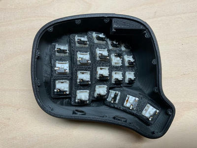
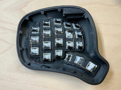
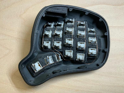
Soldering ground wire
Solder and connect one pin of each switch with this cable. Think about the cable routing so that the cable does not touch the microcontroller.
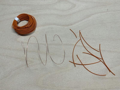
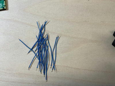
Preparing switch wires
Cut 42 pieces of copper cable with a length of 6 - 7 cm. Remove the insulation from the ends and tin the cables.
Left housing - Solder cables to sockets
Solder one end of each cable to the free pins of each socket. Bend the cables so that all ends point outwards and do not lie under the slide-in module.
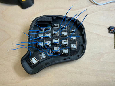
Left housing - Connect to Pico
Insert the slide-in module into the case. Connect and solder the switch cables to the inputs of the Raspberry Pi Pico. Start with the first unused pin in the upper left corner and avoid the marked ground pins. It doesn't matter which key you connect to which input.
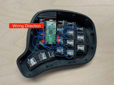
Left housing - Ground and magnets
Always make sure that no unwanted connections are made. If in doubt, separate closely spaced wires and pins that should not touch with insulating tape or other suitable material.
Connect the common ground wire of the switches to GND. For example the 8th pin from the top on the right side of the Pico.
Place four additional magnets on top of the already existing magnets.
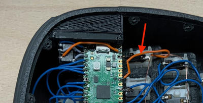
Right housing - Solder cables to sockets
Solder one end of the cables to the free pins of the hot-plug sockets and then bend the cables so that all ends point outwards and do not lie under the slide-in module.
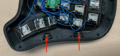
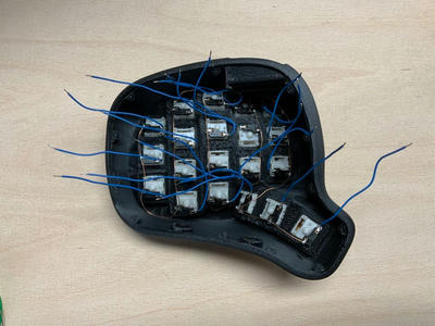
Right housing - Connect to Pico
Insert the slide-in module into the case. Now connect and solder the cables to the inputs of the Raspberry Pi Pico. Start with the first unused pin in the upper left corner and avoid the marked ground pins. It doesn't matter which key you connect to which input.
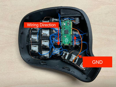
Right housing - Ground and magnets
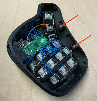
Connect the common wire of the switches to GND. For example the 8th pin from the top on the right side of the Pico.
Place four additional magnets on top of the already existing magnets.
Base Plates
Rubber feet
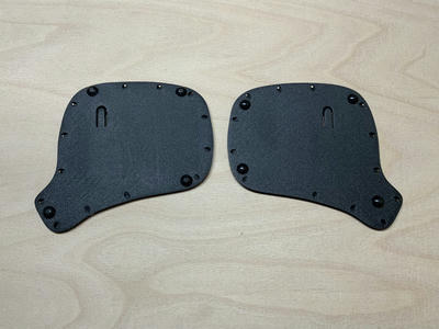
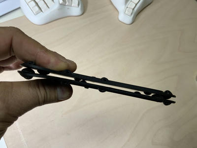
Glue four rubber feet slightly offset under each of the base plates.
When you place the base plates on top of each other, the feet should not touch.
Magnetic functions
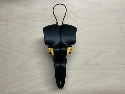
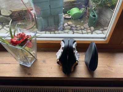
The keyboard cases and also the wrist rests have magnets in the bottoms. Thus, the keyboard halves stick to each other when you put the bottoms together.
If the parts stick together you can stow the keyboard away or use it as an an eye-catcher.
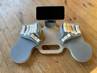
You can also use the magnets to attach the keyboard to a magnetic surface. Here is an early prototype, for which I made a wooden board. Magnets are embedded in the plate to hold the keyboard parts.
Magnet alignment
In order for the keyboard halves to stick together, you must align the magnets accordingly. For example, in the keyboard housing and the wrist rest on the left side, the north pole of the magnets points upwards and in the other half, downwards.
Inserting magnets
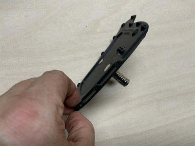
Use superglue to glue the magnets into the holes. It may help if you hold the remaining magnets from the bottom against the plate.
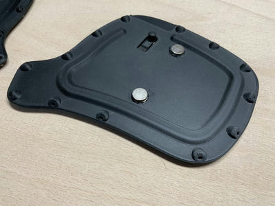
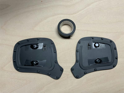
Additional magnets and tape
After the glue has dried, put an additional magnet onto each one on top.
Then put insulating tape over the magnets.
Attaching the base plates
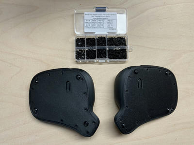
Screw the base plates under the keyboard housings using 13 x M2 x 5 mm screws
Wrist Rests
Rubber feet
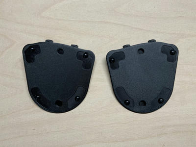
Attach four rubber feet under each wrist rest. Place the feet slightly offset so that they do not rest on top of each other when you place the wrist rests together bottom to bottom.
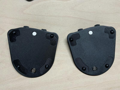
Base magnets
Glue two magnets into each of the holes using super glue. Make sure that these magnets have the same orientation as the magnets in the keyboard housing to which the wrist rest will later snap.
Front magnets
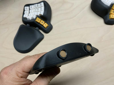
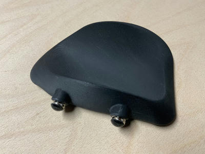
Now it's time for the magnets at the front end of the wrist rests. You need at least 10 per wrist rest. Put five in each hole. Align the magnets so that they are attracted by the magnets in the keyboard half. Usually it is enough to press the magnets in. You don't have to glue them.
Distance adjustment
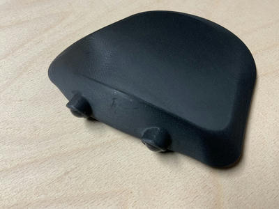
If you don't want to change the distance between the wrist rest and the keyboard, then stick one of the rubber feet directly onto each of the magnets you just inserted.
You can also add more magnets and attach the rubber feet to the last magnets. In this way, you can change the distance between the wrist rest and the keyboard by adding or removing magnets.
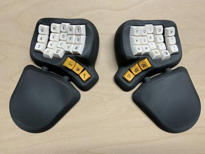
Congratulations!
You have now completely assembled the keyboard hardware. Together with the wrist rests it should look like this:
Firmware and Configuration
Circuit Diagram
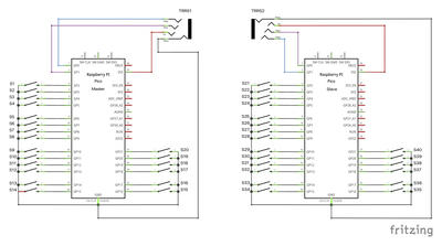
The PicoSplit consists of two halves, each equipped with a Raspberry Pi Pico. Both halves communicate with each other via a serial interface using a TRRS cable. Only one of the two halves has to be connected to the computer with a USB cable (the master keyboard).
This is the circuit diagram for the PicoSplit, with a total of 40 switches.
The wiring is the same for both halves except for the send and receive lines of the serial port. The half that connects to the computer gets a different firmware, but you can decide which half that should be. The master keyboard is the one which is connected to the computer. The other half is the slave keyboard.
Installation
The PicoSplit-Firmware is based on CircuitPython version 7.1. Previous versions do not work. Go to https://circuitpython.org/board/raspberry_pi_pico/ and install CircuitPython on both keyboard halves. Then proceed with the next steps.
Slave
Connect the slave keyboard to your computer.
A USB drive with the name CIRCUITPY appears inside the Finder (macOS) or Explorer (Windows).
Copy the files and folders inside the Slave folder of this repository to that drive.
Disconnect the slave keyboard.
Master
Connect the master keyboard to your computer.
A USB drive with the name CIRCUITPY appears inside the Finder (macOS) or Explorer (Windows).
Copy the files and folders inside the Master folder of this repository to that drive.
Disconnect the slave keyboard.
Quick function test
Keep the master keyboard connected to the computer and connect the slave keyboard to the master keyboard with a TRRS cable.
Open an text editor
Press all the keys on your keyboard one after the other.
Each time you press a key, a number should appear in the text editor and then the cursor should jump to the next line.
If no number appears when you press a key, check the wiring of the corresponding key.
Operating Modes
The keyboard has a maintenance mode:
If the PicoSplit is not in maintenance mode, it is a single keyboard device.
If it is in maintenance mode, it shows up as a keyboard and as a USB memory drive.
The keyboard is automatically in maintenance mode if no mapping.js file is on the memory drive. You can manually enter maintenance mode by resetting or reconnecting the keyboard to the computer while holding down a key. With the default PicoSplit layout, you can press the Special layer key (number 17), then tap Esc (number 18) while still holding down the Special layer key.
If you want to always boot the keyboard in maintenance mode set maintenance_mode to True at the beginning of boot.py.
maintenance_mode = True
Mapping Hardware Keys
The PicoSplit firmware is designed to make the wiring of the keyboard as simple as possible. For example: the keys don't have to be connected to specific pins of the microcontroller in order to match a certain key arrangement. This makes it easier to build handwired keyboards, because you can connect any key to any pin, as long as you use the pins you specified in the firmware.
The numbers you see when doing the quick function test are hardware key numbers. These hardware key numbers are mapped to standardized key numbers, which are used in the keyboard layout definition file (layout.js). This way you can use the same layout with differently wired keyboards.
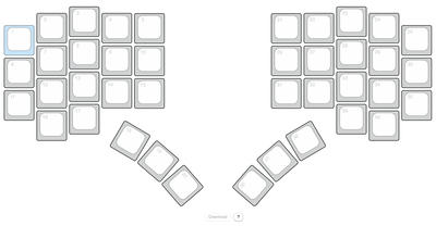
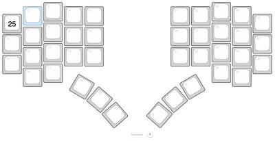
The mapping from hardware key numbers to layout key numbers cannot be done automatically, because the system does not know how the keys are wired. But there is a tool for this task. Open the file PinMapper.html in a web browser and you will see the following page:
These are all the keys on the PicoSplit keyboard. The small number in the top left corner is the key number which is used inside the layout definition file (layout.js). To map the hardware key numbers to those numbers, press the key on your keyboard that is highlighted in blue.
The recorded hardware key number is now visible at the center of the key (here 25). Then the next key is highlighted. Continue until you have pressed all the keys. You can always select a key with the mouse to change incorrect entries. When you have pressed all the keys, click the Download button. This will save a mapping.js file in your downloads folder. Copy this file to the memory drive of your keyboard.
If a mapping.js file exists, the keyboard stops emitting hardware key numbers and instead emits the key codes defined by the rules in layout.js.
Layout Definition
The keyboard layout is defined in layout.js. If you wonder why these and other files have the extension .js: They can be loaded as Javascript into a locally opened HTML page. For example: PinMapper.html uses this mechanism to read the key positions from keypositions.js. There is actually no HTML based tool for managing layout.js.
Sections
layout.js consists of sections. Each section begins with a section keyword in one line and ends with the next empty line. These are the three available section types:
keyboard
layout
layer
The order and count is important. It starts with the keyboard section, followed by a layout section and finally one or more layer sections.
Keyboard section
The keyboard section defines some timeouts which apply to all keys.
keyboard
tap_timeout=0.15
long_tap_timeout=0.4
To describe these values, I have to talk about the various action triggers first. The PicoSplit firmware supports three triggers for each key:
tap
long_tap
hold
A tap action is triggered when you press and release a key before tap_timeout (in seconds).
A long tap action is triggered when you press a key longer than tap_timeout but release it before long_tap_timeout (in seconds). In combination with the Shift action, which will be described later, you can type a capital letter, just by holding the key down a little longer.
A hold action is immediately triggered when you press a key. If you release the key before long_tap_timeout the hold action is released before a tap or long tap is triggered. If you press the key longer than long_tap_timeout, the hold action is released when you release the key. Its action does not affect a tap or long tap if it emits modifier keys or switches to another layer.
You are probably wondering what this is good for? With the hold action you can assign modifiers to keys which are normally used to type characters. The PicoSplit keyboard uses hold actions to put all modifiers on the home position keys. Hold actions are also used to activate some layers.
Layout section
The layout section has just one property, the name of the layout. Currently layout.js can have only one layout section.
layout
name=US macOS
Layer section
A layer has a name. It contains rules for action triggers (tap, long_tap or hold). There must be at least one layer - the base layer - and you can define multiple additional layers. Only one layer can be active at any time. However, rules do not have to be defined for all keys on each layer. For keys without a rule, the rule from the base layer is used.
Here is an example with all three action triggers and all available actions:
layer
name=Base
1 : tap=Codes[ Q ] : long_tap=Shift
6 : tap=Codes[ A ] : long_tap=Shift : hold=Codes[ LEFT_GUI ]
17 : tap=ChangeLayer( Special )
layer
name=Special
18 : tap=ResetKeyboard
layer
name=Umlaut
6 : tap=Sequence[Codes[ LEFT_ALT, U ]; Codes[ A ]] : long_tap=Sequence[Codes[ LEFT_ALT, U ]; Codes[ LEFT_SHIFT, A ]] : hold=Codes[ LEFT_GUI ]
A line which defines rules for a key starts with the key number followed by at least one rule. A rule consists of the trigger name (tap, long_tap or hold) followed by the equal sign and the action. Rules are separated by colons.
Actions
Codes[ < Keycode >, < Keycode >, … ] Emits the given key codes at the same time.
Sequence[ < Action > ; < Action > ] Emits the given actions one after the other. Sequences are currently not nestable and are only tested with Code actions. Note: The separator between actions inside sequences is a semicolon.
Shift Can be triggered by a long_tap and is only usefull if a tap action exists. It triggers the tap action and emits the key code of the shift key at the same time. This is used to emit capitalized letters on a long tap.
ChangeLayer( < layer name > ) Activates the layer with the given name as long as the trigger (tap or hold) is active.
ResetKeyboard Resets the keyboard.
Key codes
This is an overview of all available keycodes you can use inside layout.js
Characters
| Code | Symbol | Symbol with Shift |
|---|---|---|
| A | a | A |
| B | b | B |
| C | c | C |
| D | d | D |
| E | e | E |
| F | f | F |
| G | g | G |
| H | h | H |
| I | i | I |
| J | j | J |
| K | k | K |
| L | l | L |
| M | m | M |
| N | n | N |
| O | o | O |
| P | p | P |
| Q | q | Q |
| R | r | R |
| S | s | S |
| T | t | T |
| U | u | U |
| V | v | V |
| W | w | W |
| X | x | X |
| Y | y | Y |
| Z | z | Z |
Numbers
| Code | Symbol | Symbol with Shift |
|---|---|---|
| ONE | 1 | ! |
| TWO | 2 | @ |
| THREE | 3 | # |
| FOUR | 4 | $ |
| FIVE | 5 | % |
| SIX | 6 | ^ |
| SEVEN | 7 | & |
| EIGHT | 8 | * |
| NINE | 9 | ( |
| ZERO | 0 | ) |
Special Characters
| Code | Symbol | Symbol with Shift |
|---|---|---|
| MINUS | - | _ |
| EQUALS | = | + |
| LEFT_BRACKET | [ | { |
| RIGHT_BRACKET | ] | } |
| BACKSLASH | \ | |
| POUND | # | ~ (Non-US keyboard) |
| SEMICOLON | ; | : |
| QUOTE | ' | " |
| GRAVE_ACCENT | ` | ~ |
| COMMA | , | < |
| PERIOD | . | > |
| FORWARD_SLASH | / | ? |
| CAPS_LOCK | Caps Lock |
Keypad
| Code | Symbol | Symbol with Shift |
|---|---|---|
| KEYPAD_NUMLOCK | Num Lock (Clear on Mac) | |
| KEYPAD_FORWARD_SLASH | Keypad / | |
| KEYPAD_ASTERISK | Keypad * | |
| KEYPAD_MINUS | Keyapd - | |
| KEYPAD_PLUS | Keypad + | |
| KEYPAD_ENTER | Keypad Enter | |
| KEYPAD_ONE | Keypad 1 | End |
| KEYPAD_TWO | Keypad 2 | Down Arrow |
| KEYPAD_THREE | Keypad 3 | PgDn |
| KEYPAD_FOUR | Keypad 4 | Left Arrow |
| KEYPAD_FIVE | Keypad 5 | |
| KEYPAD_SIX | Keypad 6 | Right Arrow |
| KEYPAD_SEVEN | Keypad 7 | Home |
| KEYPAD_EIGHT | Keypad 8 | Up Arrow |
| KEYPAD_NINE | Keypad 9 | PgUp |
| KEYPAD_ZERO | Keypad 0 | Ins |
| KEYPAD_PERIOD | Keypad . | Del |
| KEYPAD_BACKSLASH | Keypad \ | |
| KEYPAD_EQUALS | Keypad = (macOS) |
Whitespaces
| Code | Symbol |
|---|---|
| ENTER | Enter (Return) |
| RETURN | Alias for ENTER |
| ESCAPE | Escape |
| TAB | Tab and Backtab |
| SPACEBAR | Spacebar |
| SPACE | Alias for SPACEBAR |
Insert and Delete
| Code | Function |
|---|---|
| INSERT | Insert |
| DELETE | Delete forward |
| BACKSPACE | Delete backward (Backspace) |
Function
| Code | Function |
|---|---|
| F1 | Function key F1 |
| F2 | Function key F3 |
| F3 | Function key F3 |
| F4 | Function key F4 |
| F5 | Function key F5 |
| F6 | Function key F6 |
| F7 | Function key F7 |
| F8 | Function key F8 |
| F9 | Function key F9 |
| F10 | Function key F10 |
| F11 | Function key F11 |
| F12 | Function key F12 |
| F13 | Function key F13 (macOS) |
| F14 | Function key F14 (macOS) |
| F15 | Function key F15 (macOS) |
| F16 | Function key F16 (macOS) |
| F17 | Function key F17 (macOS) |
| F18 | Function key F18 (macOS) |
| F19 | Function key F19 (macOS) |
Navigation
| Code | Function |
|---|---|
| HOME | Home (often moves to beginning of line) |
| PAGE_UP | Go back one page |
| END | End (often moves to end of line) |
| PAGE_DOWN | Go forward one page |
| RIGHT_ARROW | Move the cursor right |
| LEFT_ARROW | Move the cursor left |
| DOWN_ARROW | Move the cursor down |
| UP_ARROW | Move the cursor up |
Modifiers
| Code | Function |
|---|---|
| LEFT_CONTROL | Control modifier left of the spacebar |
| CONTROL | Alias for LEFT_CONTROL |
| LEFT_SHIFT | Shift modifier left of the spacebar |
| SHIFT | Alias for LEFT_SHIFT |
| LEFT_ALT | Alt modifier left of the spacebar |
| ALT | Alias for LEFT_ALT; Alt is also known as Option (macOS) |
| OPTION | Labeled as Option on some Mac keyboards |
| LEFT_GUI | GUI modifier left of the spacebar |
| GUI | Alias for LEFT_GUI; GUI is also known as the Windows key, Command (macOS), or Meta |
| WINDOWS | Labeled with a Windows logo on Windows keyboards |
| COMMAND | Labeled as Command on Mac keyboards, with a clover glyph |
| RIGHT_CONTROL | Control modifier right of the spacebar |
| RIGHT_SHIFT | Shift modifier right of the spacebar |
| RIGHT_ALT | Alt modifier right of the spacebar |
| RIGHT_GUI | GUI modifier right of the spacebar |
Others
| Code | Function |
|---|---|
| PRINT_SCREEN | Print Screen (SysRq) |
| SCROLL_LOCK | Scroll Lock |
| PAUSE | Pause (Break) |
| APPLICATION | Application: also known as the Menu key (Windows) |
| POWER | Power (macOS) |