Step by Step Instructions
Magnets
Start by gluing two of the magnets into the designated spots with super glue. Hold the badge against it from behind so that the alignment of the magnets is correct. The magnets in the badge must attract the magnets in the keypad.


Inserts
The two inserts hold the badge in place. Glue them in with superglue.


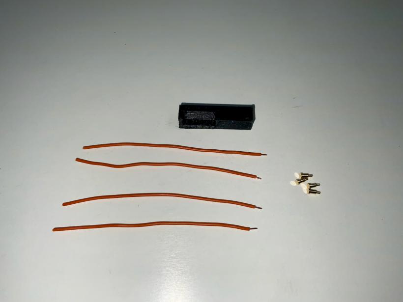
Connector preparation
Before you start working on the Pogo Pins, make sure that the connector can be inserted into the designated hole with some force. It should not be too loose so that you can adjust its position later on. If the part doesn't fit tightly into the hole, try printing it again with different settings.


The connector should slide easily into the back of the badge.

Pogo Pins
This is the first project I've used pogo pins in and I actually thought they would be difficult to handle, but it ends up being quite simple. You can solder the cables against the back of the pins whith the help of a third hand.


The holes in the connector are often too small for the Pogo Pins. You can widen them a bit with a pair of pointed tweezers. But not too much. You should be able to insert them with a little pressure.

Make sure all pins stick out about the same length.

Use superglue on the backside to fix the pins, but do not use too much glue so that the spring mechanism is not damaged.

Insulate the cable connections with thin heat shrink tubing.


First insert the connector into the top part from above and then place the badge on the top part. Now press the connector from behind against the circuit board of the badge so that the pogo pins are pressed.


Remove the badge and make sure the connector is straight in the top. When you are satisfied with its position, glue it in place with a little superglue.

IO Expander
Der IO expander is a small PCB with an MCP23017 on it. Because there are so many different modules with this IC, I didn't provide a mount for it. I simply attached my module with hot glue, making sure that the labeling is visible.


The following pictures show you how to connect the cables from the connector to the MCP23017 module.


All address pins are connected to GND

Reset is connected to VCC

Key switches
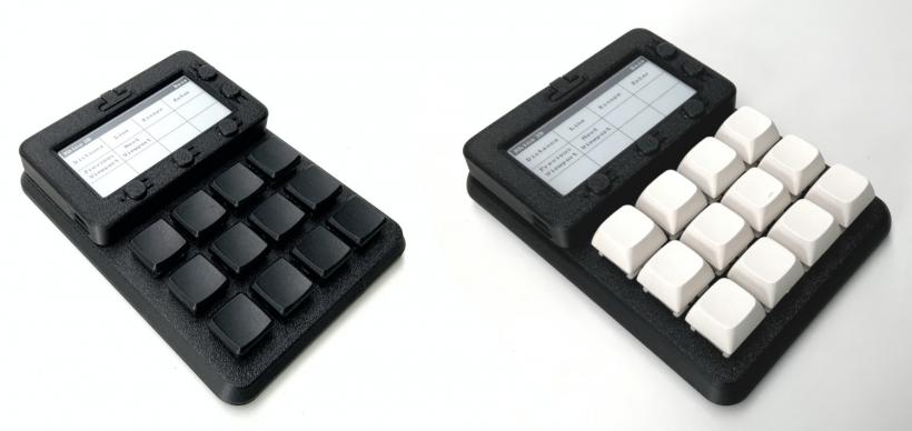
Insert twelve key switches. You can use MX-style key switches or low profile key switches from Kailh (I only tested the original low profile keys, not version 2).

Put sockets on the connectors of the switches if you want to change them at a later time. But even if you don't want to change them, I recommend the sockets, because you can solder the cables to them more easily.


Connect one pin of each switch to GND
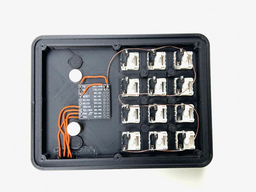
Connect the second pin of each switch to an input of the MCP23017 module. You can use all inputs except the last four (B4, B5, B6 and B7). Which key you solder to which pin does not matter.

Bottom plate
Now you're almost done with the hardware. You only have to fix the bottom plate to the top part with six 2 mm screws.