Switches
Put the keycaps on the 40 keys. If you have labeled keycaps, make sure the slot in the keycaps is on top.
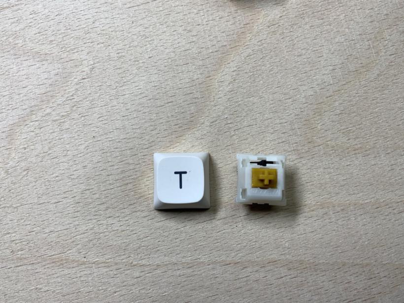
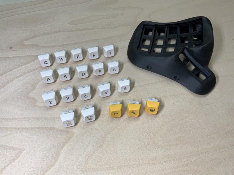
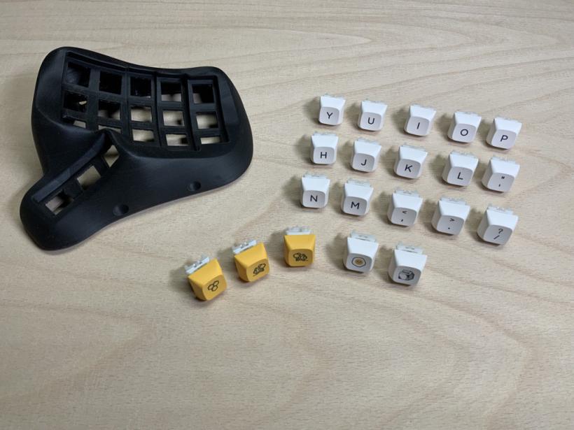
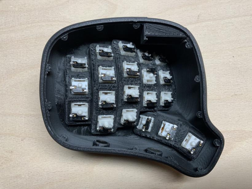
Insert the keys into the housings so that the slots are at the top. The thumb keys are the exception (see illustrations). Check whether all keys can be pressed down freely without jamming. The PicoSplit keyboard is optimized for short finger travel, so the keys are as close together as possible. If some keys do stick, then it may help if you rotate them. Normally nothing should stick, but you have to do this test now, because the keys will be soldered in the next step and then the alignment can't be changed anymore.
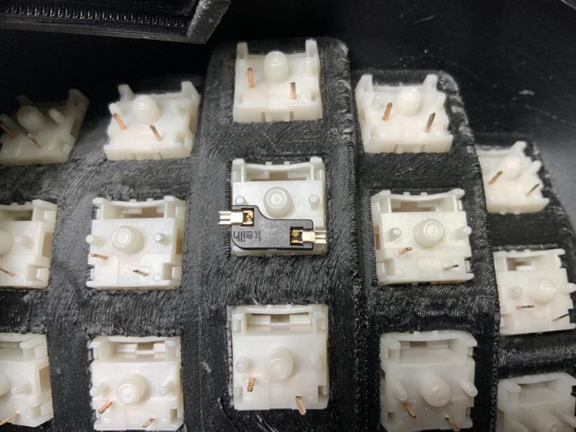
Now put the hot plug sockets onto the pins of the keys.
Insert the slide-in modules with the microcontrollers every now and then for test purposes, and make sure that the socket contacts do not touch the board.
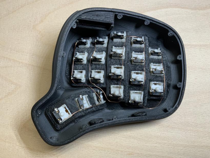
Soldering the wires for common ground
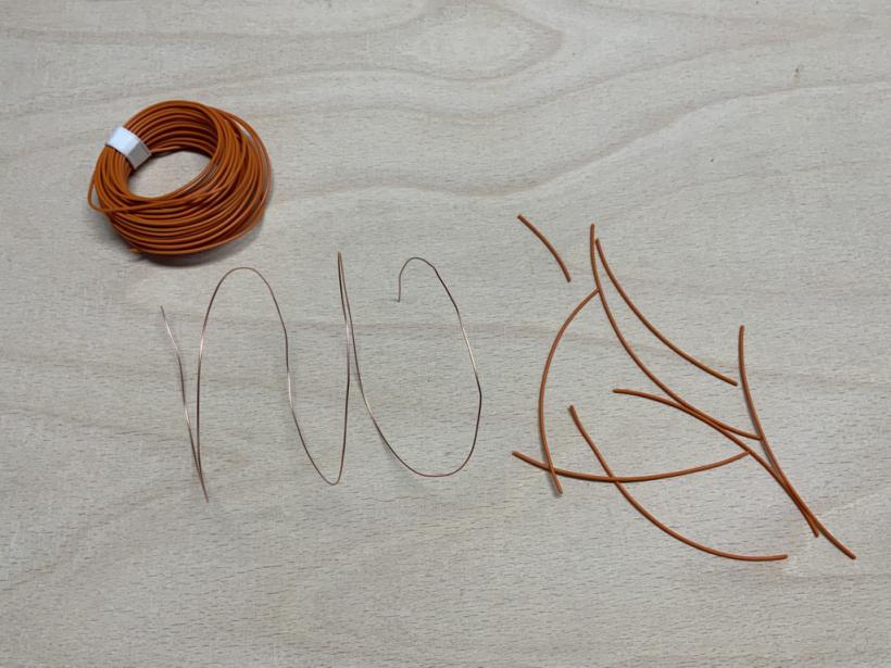
Now you need a piece of the copper cable with a length of about 70 cm. Remove the insulation from the cable.
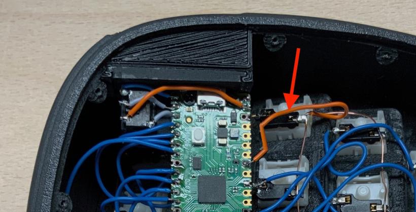
Soldering the wires for the supply voltage
Now you need a piece of the copper cable with a length of about 70 cm. Remove the insulation from the cable.
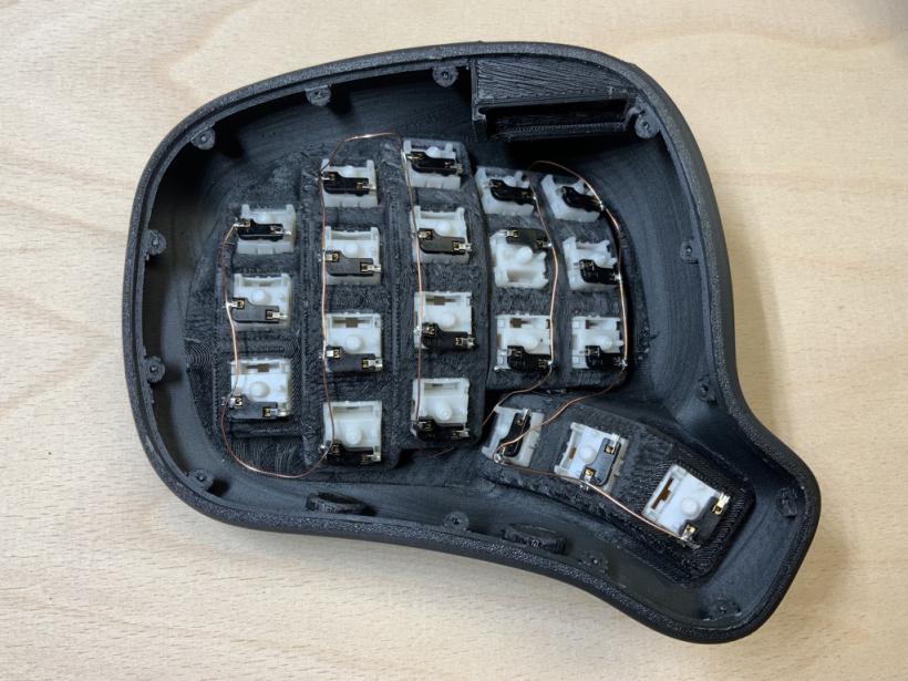
Solder and connect one pin of each switch with this cable. Think about the cable routing so that the cable does not touch the microcontroller.
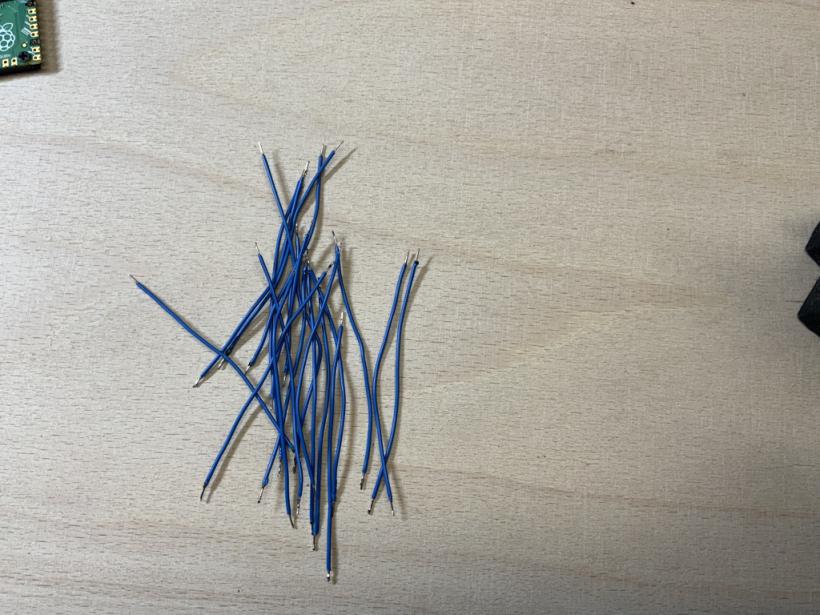
Soldering the switch cables
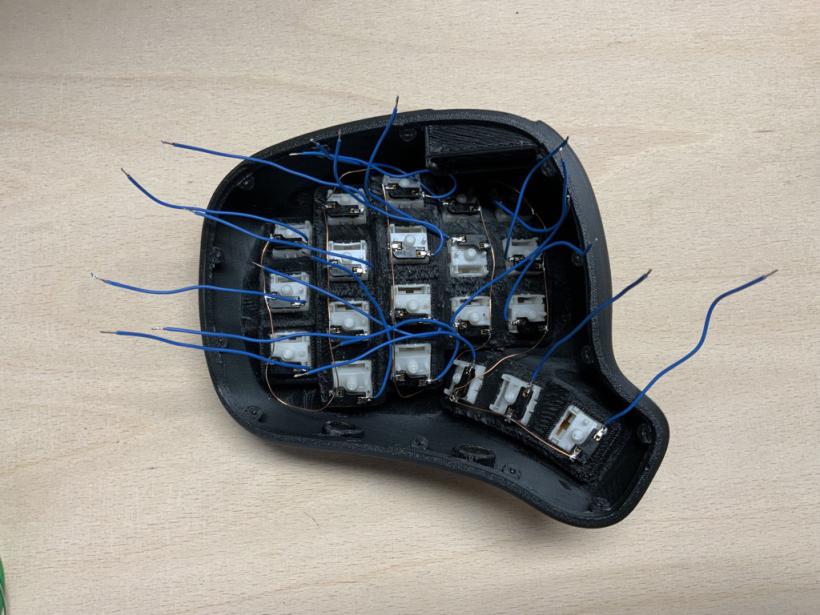
Cut 42 pieces of copper cable with a length of 6 - 7 cm. Remove the insulation from the ends and tin the cables.
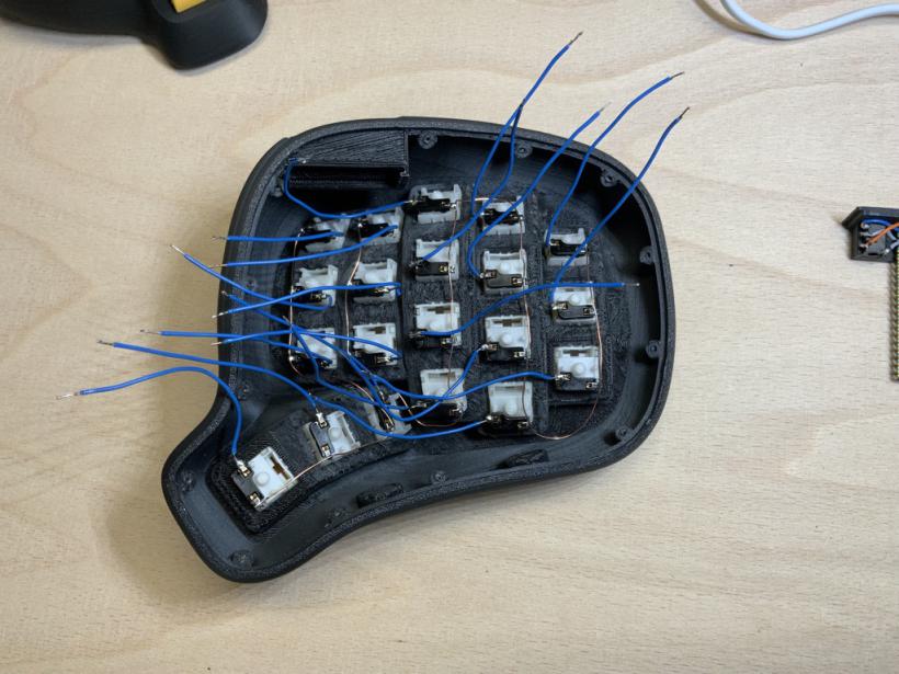
Left housing
Solder one end of each cable to the free pins of each socket. Bend the cables so that all ends point outwards and do not lie under the slide-in module.
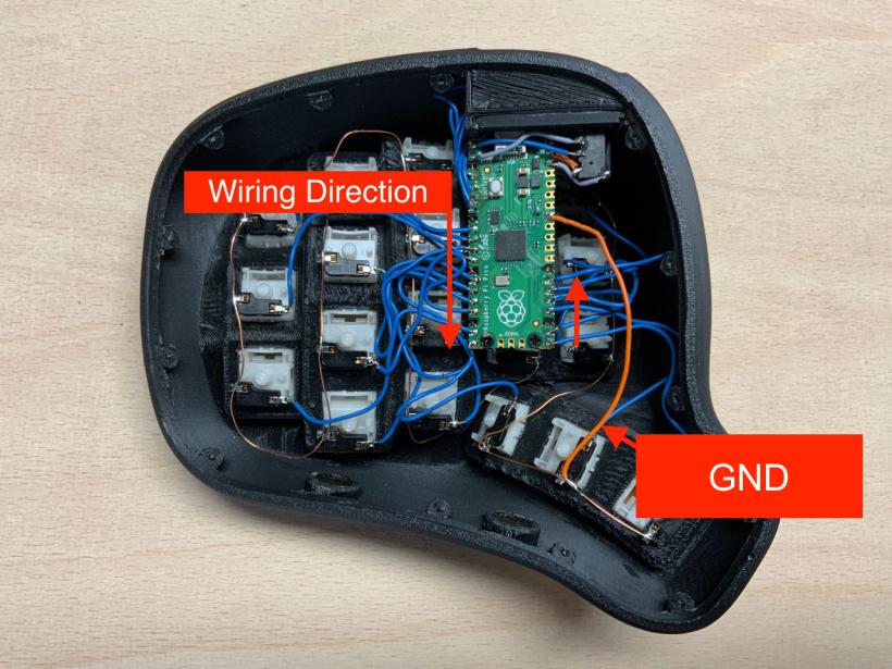
Now insert the slide-in module into the case. Connect and solder the switch cables to the inputs of the Raspberry Pi Pico. Start with the first unused pin in the upper left corner and avoid the marked ground pins. It doesn't matter which key you connect to which input.
Always make sure that no unwanted connections are made. If in doubt, separate closely spaced wires and pins that should not touch with insulating tape or other suitable material.
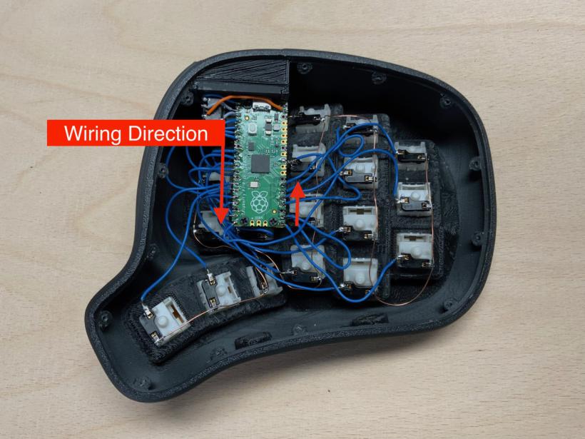
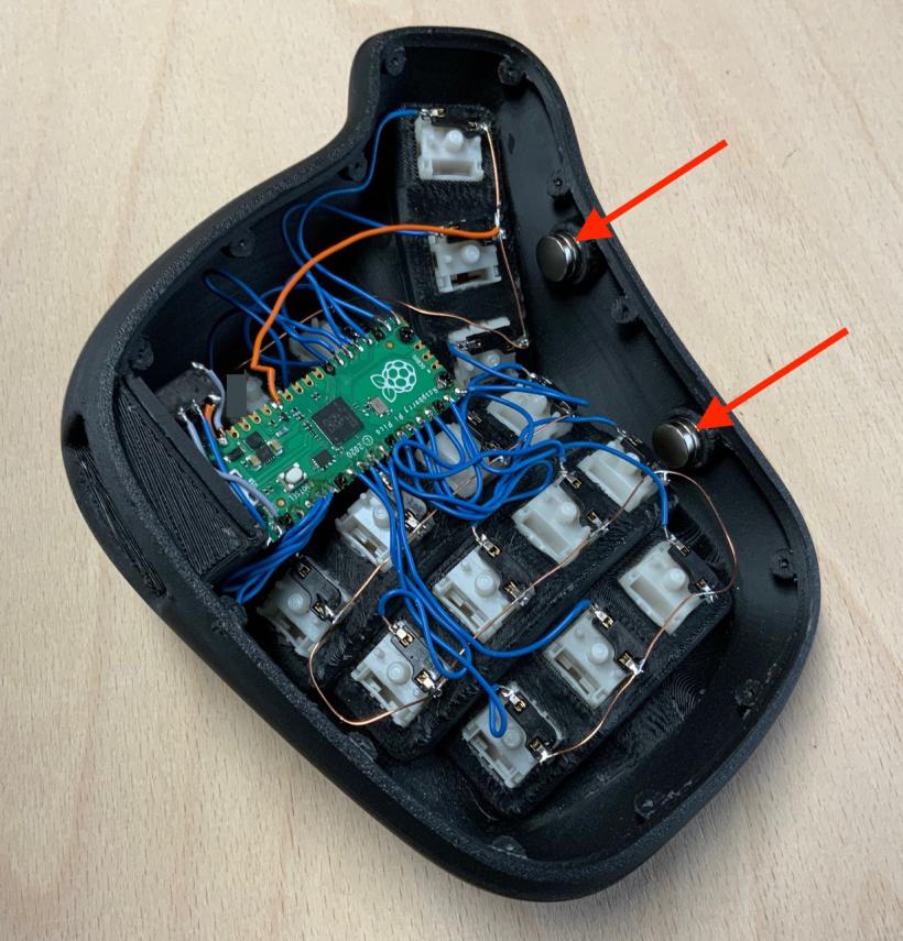
Connect the common wire of the switches to GND. For example the 8th pin from the top on the right side of the Pico.
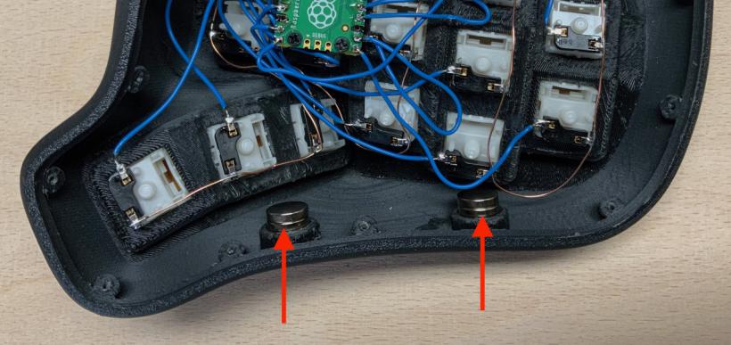
Place four additional magnets on top of the already existing magnets.
Right housing
Solder one end of the cables to the free pins of the hot-plug sockets and then bend the cables so that all ends point outwards and do not lie under the slide-in module.
Insert the slide-in module into the case. Now connect and solder the cables to the inputs of the Raspberry Pi Pico. Start with the first unused pin in the upper left corner and avoid the marked ground pins. It doesn't matter which key you connect to which input.
Connect the common wire of the switches to GND. For example the 8th pin from the top on the right side of the Pico.
Place four additional magnets on top of the already existing magnets.